Internal jumpers, switches, and audio cables, Processor circuit board – Grass Valley PDR100 User Manual
Page 46
Chapter 3 Mechanical Installation
3-22
PDR100 Installation
Internal Jumpers, Switches, and Audio Cables
The PDR100 is designed to provide as much flexibility as possible. To accomplish
this, plug jumpers and DIP (dual in-line package) switches have been designed in to
allow for a number of operating conditions. The factory settings are optimum for most
applications. However, it is always possible that the PDR100 may be required to
operate in a slightly altered operating environment.
The following paragraphs provide the information on how plug-jumpers and the DIP
switches for each of the circuit boards can be re-configured or returned to the correct
positions if they have been moved.
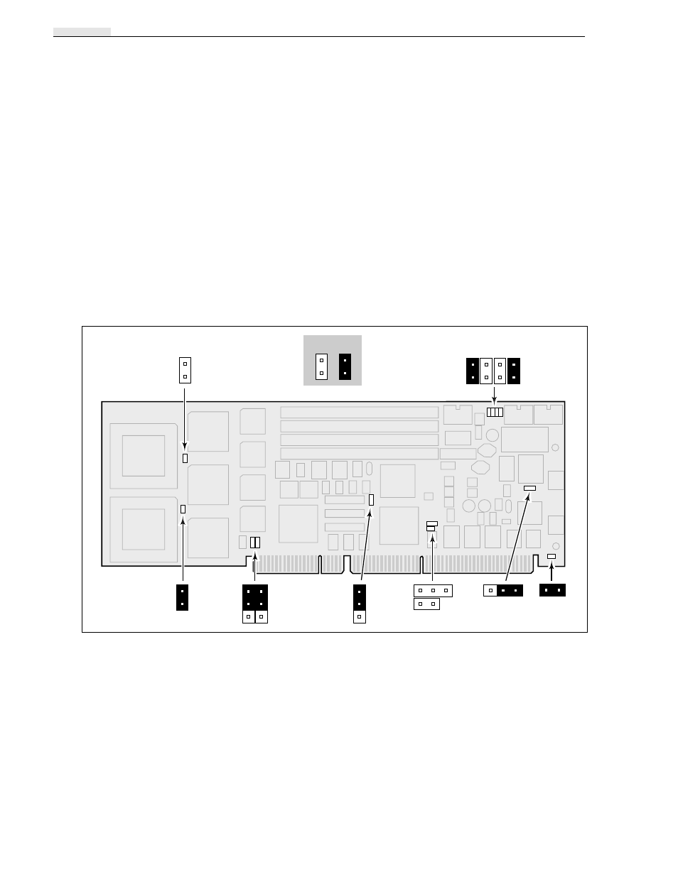
Processor Circuit Board
Jumpers on the Processor circuit board allow the board to be used in a variety of
systems. Figure 3-23 shows the jumper locations and the factory settings for use in
the PDR100.
Figure 3-23. Processor Circuit Board Showing the Jumper Locations
9040-14
E9
E11
E7 E2 E3 E4
E5
E6
E1
E8
E13
E12
E10
Off
On