Typical configurations, Serial four-channel in and four-channel out, Chapter 2 configuration – Grass Valley PDR100 User Manual
Page 22
Chapter 2 Configuration
2-6
PDR100 Installation
Typical Configurations
The majority of the PDR100’s will use one of the following typical configurations.
Processor and Disk Recorder circuit boards remain constant throughout the
configurations.
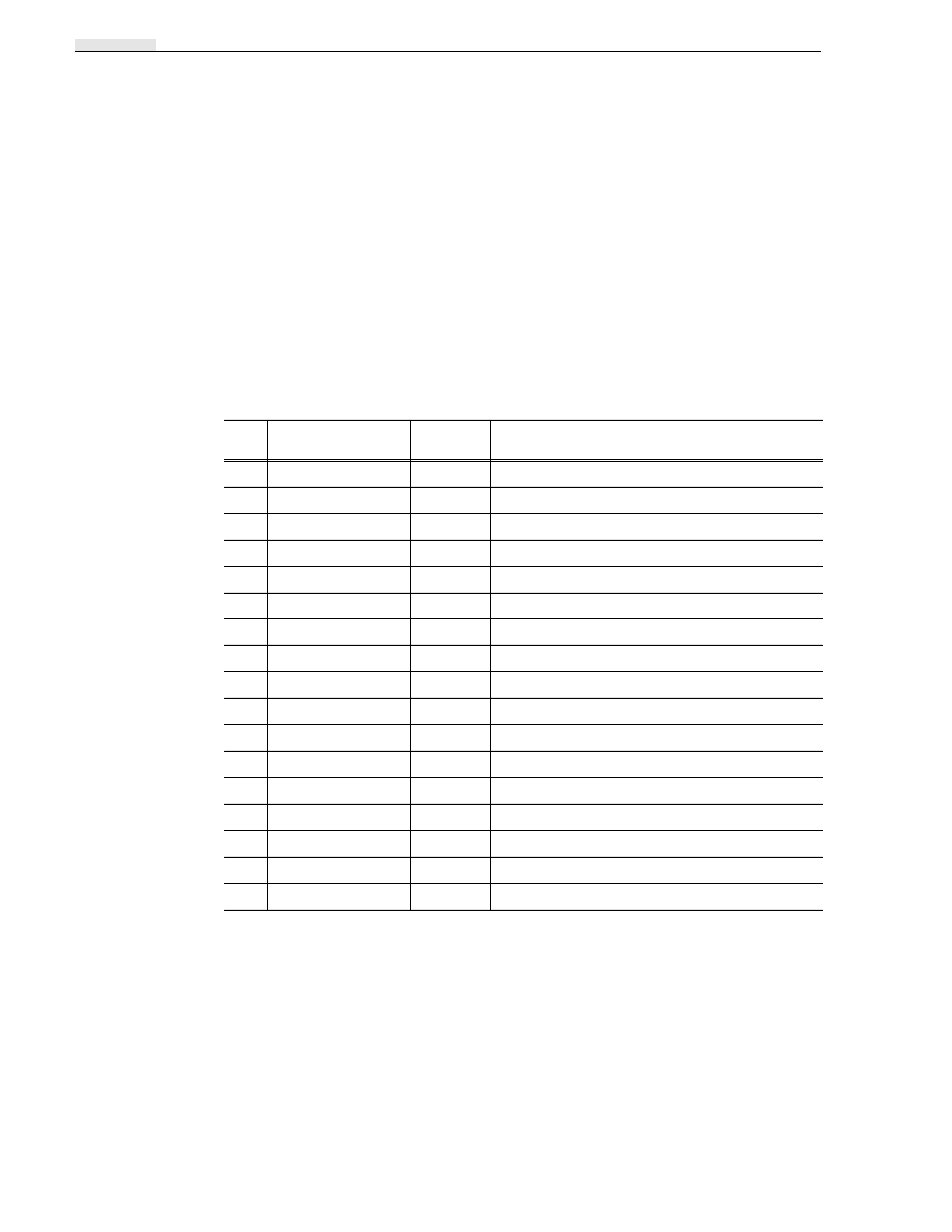
Serial Four-Channel In and Four-Channel Out
This is Option 40 in the standard factory configurations. The Serial I/O circuit boards
have two-channel input and output each; two I/O circuit boards and four audio circuit
boards are required for this configuration. See Table 2-1. This configuration uses
eight hard disk drives and two Disk Recorder (Master and Slave) circuit boards to
support four-channel operation.
Table 2-1. Circuit Boards for Serial Four-CH In/Four-CH Out
Slot
Board Name
Dedicated
Location
Miscellaneous
J1
Processor
Yes
EISA & ISA
J2
VGA-I/O
Yes
ISA
J3
Empty
—
J4
Empty
—
J5
Empty
—
J6
Empty
—
J7
Empty
—
J8
Serial I/O
No
Two Video Channels In & Two Video Channels Out
J9
Audio
No
Four Audio Channels
J10
Audio
No
Four Audio Channels
J11
Serial I/O
No
Two Video Channels In & Two Video Channels Out
J12
Audio
No
Four Audio Channels
J13
Audio
No
Four Audio Channels
J14
Master Disk Recorder
Yes
Controls four, eight, or twelve hard disks
J15
Slave Disk Recorder
Yes
Controls four, eight, or twelve hard disks
J16
Reference Genlock
Yes
J17
RS-422 I/O
Yes