Decoder circuit board, Chapter 3 mechanical installation – Grass Valley PDR100 User Manual
Page 62
Chapter 3 Mechanical Installation
3-38
PDR100 Installation
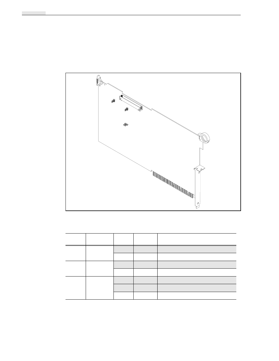
Decoder Circuit Board
The Decoder circuit board, which is paired with the Analog Composite Input circuit
board, is optional and can occupy various slots from J3 to J13.
The Decoder circuit board has three plug jumpers for test purposes. See Figure 3-35.
Figure 3-35. Decoder Circuit Board Showing Plug Jumpers
a.
Decoder board with the -01 or higher suffix level are compatible only with Analog Composite Input
boards 671-3081-02 or higher, and require software Version 1.3 or higher.
Table 3-14. Decoder Plug Jumpers
Jumper
Name
Position
Factory-
Installed
Operation
J1
Test Jumper
1-2
Jumpered
Operating
2-3
Developmental Position
J2
Test Jumper
1-2
Jumpered
Operating
2-3
Developmental Position
J3
Test Jumper
No Jumper
Operating position for board 671-3083-00
1-2
Jumpered
Operating position for board 671-3083-01
a
2-3
Developmental Position
J1
J2
J3
- LDK 5302 (24 pages)
- SFP Optical Converters (18 pages)
- 2000GEN (22 pages)
- 2011RDA (28 pages)
- 2010RDA-16 (28 pages)
- 2000NET v3.2.2 (72 pages)
- 2000NET v3.1 (68 pages)
- 2020DAC D-To-A (30 pages)
- 2000NET v4.0.0 (92 pages)
- 2020ADC A-To-D (32 pages)
- 2030RDA (36 pages)
- 2031RDA-SM (38 pages)
- 2041EDA (20 pages)
- 2040RDA (24 pages)
- 2041RDA (24 pages)
- 2042EDA (26 pages)
- 2090MDC (30 pages)
- 2040RDA-FR (52 pages)
- LDK 4021 (22 pages)
- 3DX-3901 (38 pages)
- LDK 4420 (82 pages)
- LDK 5307 (40 pages)
- Maestro Master Control Installation v.1.5.1 (455 pages)
- Maestro Master Control Installation v.1.5.1 (428 pages)
- 7600REF Installation (16 pages)
- 7600REF (84 pages)
- 8900FSS (18 pages)
- 8900GEN-SM (50 pages)
- 8900NET v.4.3.0 (108 pages)
- Safety Summary (17 pages)
- 8900NET v.4.0.0 (94 pages)
- 8906 (34 pages)
- 8911 (16 pages)
- 8900NET v.3.2.2 (78 pages)
- 8914 (18 pages)
- 8912RDA-D (20 pages)
- 8916 (26 pages)
- 8910ADA-SR (58 pages)
- 8920ADC v.2.0 (28 pages)
- 8920ADC v.2.0.1A (40 pages)
- 8920DAC (28 pages)
- 8920DMX (30 pages)
- 8920ADT (36 pages)
- 8920MUX (50 pages)
- 8921ADT (58 pages)