Processor circuit board – Grass Valley PDR100 User Manual
Page 47
Processor Circuit Board
PDR100 Installation
3-23
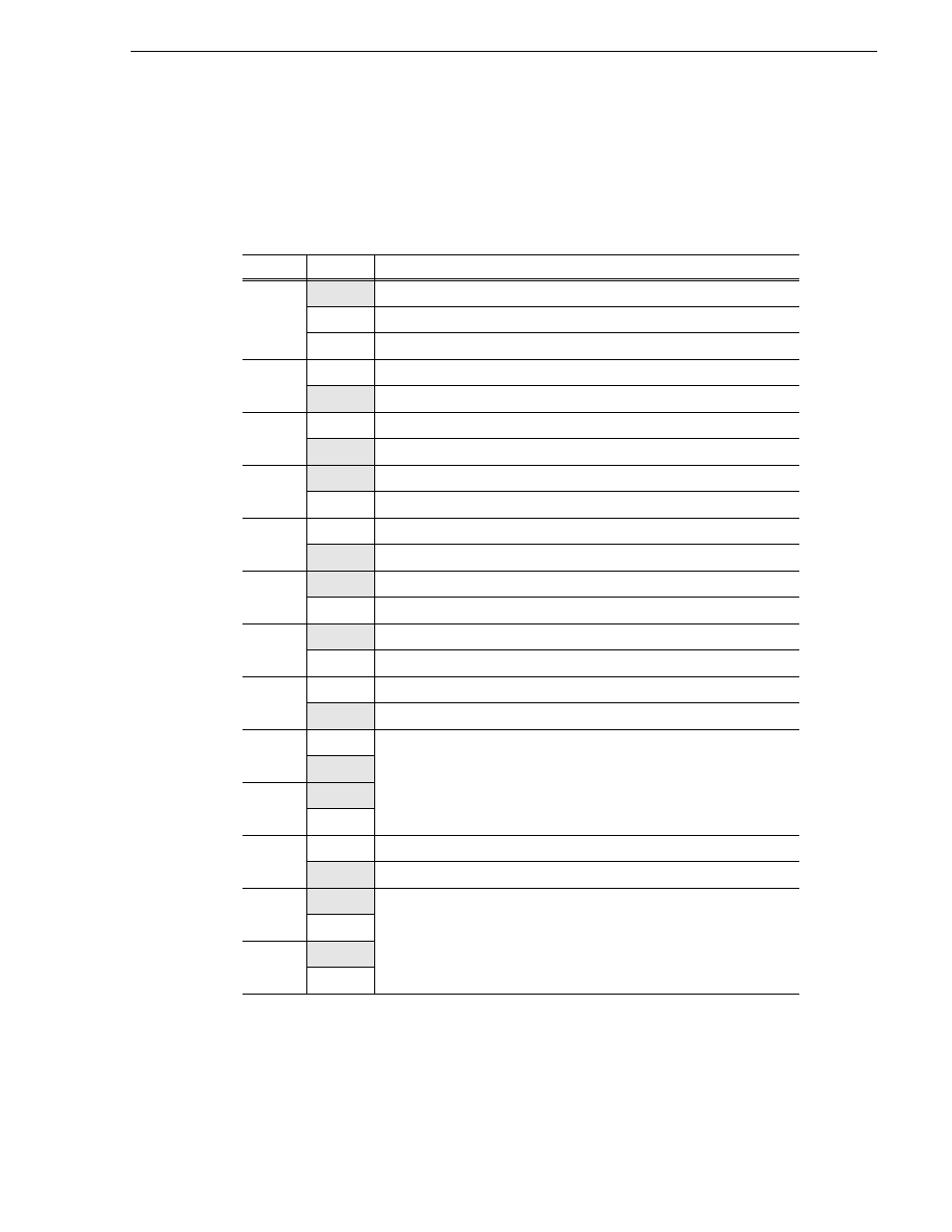
Table 3-3 lists each jumper and its function. The shaded listings are the factory
settings for the jumpers. A position of “On” or “Off” indicates whether or not the
jumper is installed. A position of “1-2” or “2-3” indicates the pins on which the
jumper is installed.
Table 3-3. Processor Board Jumper Settings
Jumper
Position
Function
E1
Off
No Interrupt
1-2
IRQ11
2-3
IRQ10
E2
On
/XT Keyboard
Off
PS/2 or /AT Keyboard
E3
On
Manufacturing Test
Off
Normal Mode
E4
On
Color Display
Off
Monochrome Display
E5
1-2
Disable BIOS 12 Volts
2-3
Enable FLASH programming
E6
On
Connect mounting bracket to CPU ground.
Off
Disconnect mounting bracket from CPU ground.
E7
On
Serial Port Mode: DTE (connect to a modem -/AT standard)
Off
Serial Port Mode: DCE (connect to a CPU)
E8
On
Dual CPU
Off
Single CPU
E9
On
Select 133MHz clock speed
Off
E10
On
E11
1-2
CPU takes priority on EISA bus.
2-3
EISA master takes priority on EISA bus - EISA bus throughput increased
E12
1-2
Select 512K Cache
2-3
E13
1-2
2-3
- LDK 5302 (24 pages)
- SFP Optical Converters (18 pages)
- 2000GEN (22 pages)
- 2011RDA (28 pages)
- 2010RDA-16 (28 pages)
- 2000NET v3.2.2 (72 pages)
- 2000NET v3.1 (68 pages)
- 2020DAC D-To-A (30 pages)
- 2000NET v4.0.0 (92 pages)
- 2020ADC A-To-D (32 pages)
- 2030RDA (36 pages)
- 2031RDA-SM (38 pages)
- 2041EDA (20 pages)
- 2040RDA (24 pages)
- 2041RDA (24 pages)
- 2042EDA (26 pages)
- 2090MDC (30 pages)
- 2040RDA-FR (52 pages)
- LDK 4021 (22 pages)
- 3DX-3901 (38 pages)
- LDK 4420 (82 pages)
- LDK 5307 (40 pages)
- Maestro Master Control Installation v.1.5.1 (455 pages)
- Maestro Master Control Installation v.1.5.1 (428 pages)
- 7600REF Installation (16 pages)
- 7600REF (84 pages)
- 8900FSS (18 pages)
- 8900GEN-SM (50 pages)
- 8900NET v.4.3.0 (108 pages)
- Safety Summary (17 pages)
- 8900NET v.4.0.0 (94 pages)
- 8906 (34 pages)
- 8911 (16 pages)
- 8900NET v.3.2.2 (78 pages)
- 8914 (18 pages)
- 8912RDA-D (20 pages)
- 8916 (26 pages)
- 8910ADA-SR (58 pages)
- 8920ADC v.2.0 (28 pages)
- 8920ADC v.2.0.1A (40 pages)
- 8920DAC (28 pages)
- 8920DMX (30 pages)
- 8920ADT (36 pages)
- 8920MUX (50 pages)
- 8921ADT (58 pages)