Jumper settings, Dip switch settings, Vga-i/o circuit board – Grass Valley PDR100 User Manual
Page 49
VGA-I/O Circuit Board
PDR100 Installation
3-25
Jumper Settings
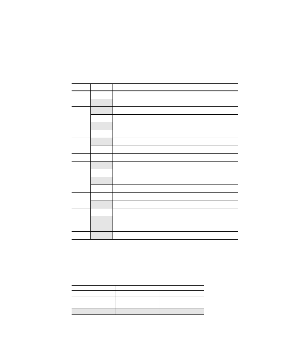
Table 3-4 lists each jumper and its function. The shaded listings are the factory
settings for the jumpers. A position of “On” or “Off” indicates whether or not the
jumper is installed. A position of “1-2” or “2-3” indicates the pins on which the
jumper is installed.
DIP Switch Settings
The VGA-I/O board has two 6-position DIP switches to define various functions. The
switch settings are shown in Figure 3-24. The tables that follow list the settings by
function.
Table 3-4. VGA-I/O Board Jumper Settings
Jumper
Position
Function
E1
On
Support 2.88M Floppy
Off
No 2.88M Floppy
E2
1-2
Selects IRQ4 for Serial Port COM1
2-3
Selects IRQ3 for Serial Port COM1
E3
1-2
Selects IRQ3 for Serial Port COM2
2-3
Selects IRQ4 for Serial Port COM2
E4
1-2
Selects IRQ7 for the Parallel Port
2-3
Selects IRQ5 for the Parallel Port
E5
Off
E6
1-2
VGA Enable
2-3
VGA Disable
E7
On
Zero Wait State Operation
Off
No Zero Wait State Operation
E8
On
IRQ9 Enabled
Off
IRQ9 Disabled
E9
On
Video Dot Clock Enabled
Off
Video Dot Clock Disabled
E10
Off
(not used)
E11
Off
(not used)
Table 3-5. Serial Port COM1 Switch Settings
SW1-5
SW1-6
Functions
On
On
Disable
On
Off
2F8h
Off
On
3E8h
Off
Off
3F8h