Connecting linear time code, Chapter 3 mechanical installation – Grass Valley PDR100 User Manual
Page 36
Chapter 3 Mechanical Installation
3-12
PDR100 Installation
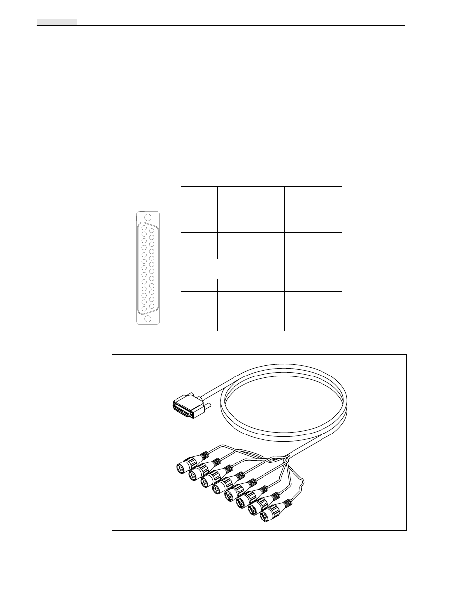
Connecting Linear Time Code
There are eight Longitudinal Time Code (LTC) interfaces (four inputs and four
outputs) incorporated in the DB25 connector on the rear panel of the Reference
Genlock circuit board. Table 3-2 lists the pin assignments for the DB25 connector.
An eight-connector DB25-XLR breakout cable (shown in Figure 3-13 is available as
an optional accessory. The XLR connectors are labeled to correspond with the inputs
and outputs listed in Table 3-2.
NOTE: The DB25-XLR breakout cable is also used to connect the Audio circuit
board to the XLR100 as described on page 3-14.
Figure 3-13. Breakout Cable for the PDR100
Table 3-2. Pin Assignments for the DB25 - XLR Adaptor Cable
Input
Channel
+ Signal
-Signal
Common
0
Pin 1
Pin 2
Pin 3
1
Pin 4
Pin 5
Pin 6
2
Pin 7
Pin 8
Pin 9
3
Pin 10
Pin 11
Pin 12
Output
Channel
0
Pin 15
Pin 16
Pin 14
1
Pin 18
Pin 19
Pin 17
2
Pin 21
Pin 22
Pin 20
3
Pin 24
Pin 25
Pin 23
Power-On Indicator Pin 13 when used with Audio card
1
13
14
25
9040-5