Operating levels, Configuration – Grass Valley NV7512 v.1.3 User Manual
Page 99
NV7512 Audio Router • User’s Guide
89
4. Configuration
Setting Analog Gain, Mute Detection and Operating Levels
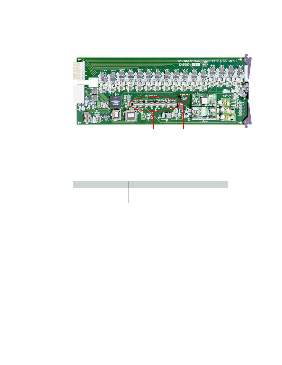
3 On the card, locate the DIP switches labeled ‘INPUT CHANNEL GAIN’, as shown in
Figure 4-4.
Figure 4-4. Analog Audio Input Card Switch and Jumper Locations
4 Using a small, pointed object, such as a ball point pen, slide the beige switch piece to ‘ON’ or
‘OFF’ as desired. Repeat this step for each of the 32 switches until all switches are set to ‘ON’
or ‘OFF’ as needed.
The following lists each switch position and the gain, maximum input level, and effective input
cap for each:
5 Locate the ‘J7’ jumper labeled ‘MUTE DETECTION’, as shown in Figure 4-4.
6 Place jumper sleeves in the ‘ON’ position to activate mute detection, or in the ‘OFF’ position to
deactivate mute detection.
7 When all switches and the jumper are set, gently slide the analog input card back into place in
the router frame.
8 When all cards are inserted back in the router, close the router door.
Operating Levels
The analog input card and analog output cards feature an additional DIP switch set that can be used
to match the operating level of the facility. For example, if the incoming signal operating level is
+24 dbu, the card can be set to +24 dbu. By matching the incoming signal level, there is less degra-
dation of the signal when it is converted to digital for internal routing in the router.
By default, all switches are set to ‘OFF’ and the operating level set to +24
dBu
. By setting the DIP
switches in specific sequences, operating levels can be set for +15
dBu
, +18
dBu
or +24
dBu
.
Input Gain
Control
Mute
Detection
Switch 1
Switch 2
System Gain
Maximum Input Level
Off
Off
0dB
+ 24dBu
On
On
+ 6 dB
+ 18dBu