Installation, Making signal connections, Figure 2-8. aes signal connections (rear view) – Grass Valley NV7512 v.1.3 User Manual
Page 56
46
Rev 1.3 • 10 Oct 08
2. Installation
Making Signal Connections
How to make AES signal connections
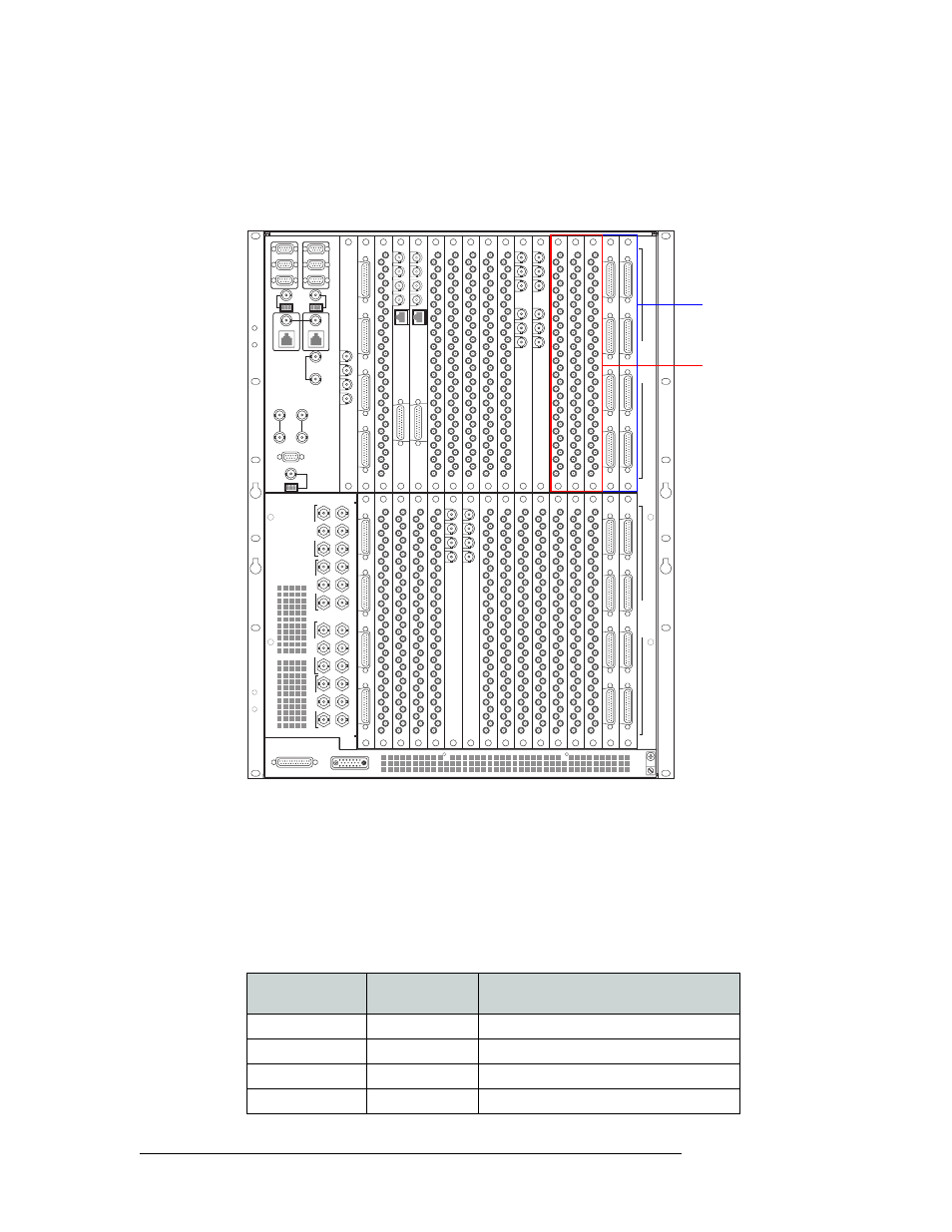
1 Locate the AES input connections at the rear of the router, as shown in Figure 2-8. Inputs are
located in the lower half of the router frame. The exact location of the backplanes and corre-
sponding connectors may be different depending on your router configuration.
Figure 2-8. AES signal connections (Rear View)
2 For each input connection, connect using the connector and cable appropriate for the type of
incoming signal:
For AES unbalanced signals, use a DIN 1.0/2.3 coax connector and 1855A Belden cable, or
equivalent.
For AES balanced signals, use NVISION’s breakout cable (NV5000-Cable1) or a DB25 con-
nector and cable with custom wiring:
This table lists which the signal associated with each wire in the breakout cable:
449-480
417-448
385-416 353-384
321-352 289-320
257-288
225-256
193-224
161-192 129-160
97-128
65-96
33-64
1-32
481-512
I
N
P
U
T
S
O
U
T
P
U
T
S
22
22
22
22
22
22
22
22
22
22
22
22
22
22
22
22
22
22
22
22
QUAD MIX
OUTPUT
ANALOG
AUDIO
OUT
10/100BT
2
3
4
QUAD MIX
OUTPUT
1
QUAD MIX
OUTPUT
ANALOG
AUDIO
OUT
10/100BT
2
3
4
QUAD MIX
OUTPUT
1
OUT 1
REF 1 OUT
REF 1 IN
OUT 2
REF 2 OUT
REF 2 IN
OUT 1
REF 1 OUT
REF 1 IN
OUT 2
REF 2 OUT
REF 2 IN
MADI
INPUT
IN 1
REF 1
IN 2
REF 2
MADI
INPUT
AES unbalanced
signals use DIN 1.0/2.3
Coax connectors
AES balanced signals
use DB25 connectors
Inputs are found in the
lower half of the router
frame
Outputs are found in
the upper half of the
router frame
Signal
Wire Number
Jacket Color
(corresponds to wire number)
Left 1
1
Brown
Right 1
2
Red
Left 2
3
Orange
Right 2
4
Yellow