Mixing analog and digital, Introduction – Grass Valley NV7512 v.1.3 User Manual
Page 15
NV7512 Audio Router • User’s Guide
5
1. Introduction
Signal Types and Rates
Output sample rates will be identical to the input sample rate. For example, if the input sample rate
is 96kHz, the output sample rate will be 96kHz.
Because unbalanced and balanced signals use different I/O connectors, the connectors used to
receive and distribute signals differ depending on the signal type.
For AES unbalanced signals, the I/O backplane passes signals through 32 individually numbered
connectors, starting at 1 and continuing sequentially up to 32. The sample rate of the signal deter-
mines how many signals a single input card supports and which coaxial connectors are used, as fol-
lows:
• If the rate is 48kHz, all 32 connectors may be used.
• If the rate is 96kHz, every other connector may be used, starting at 1 and leaving the next dis-
connected (1, 3, 5, 7, etc.). A total of 16 inputs may be used.
• If the rate is 192kHz, every fourth input may be used, starting at 1 and leaving the next three
disconnected (1, 5, 9, 13, etc.). A total of 8 inputs may be used.
For AES balanced signals, the I/O backplane passes signals through four DB25 connectors num-
bered 1-8, 9-16, 17-24 and 25-32, respectively.
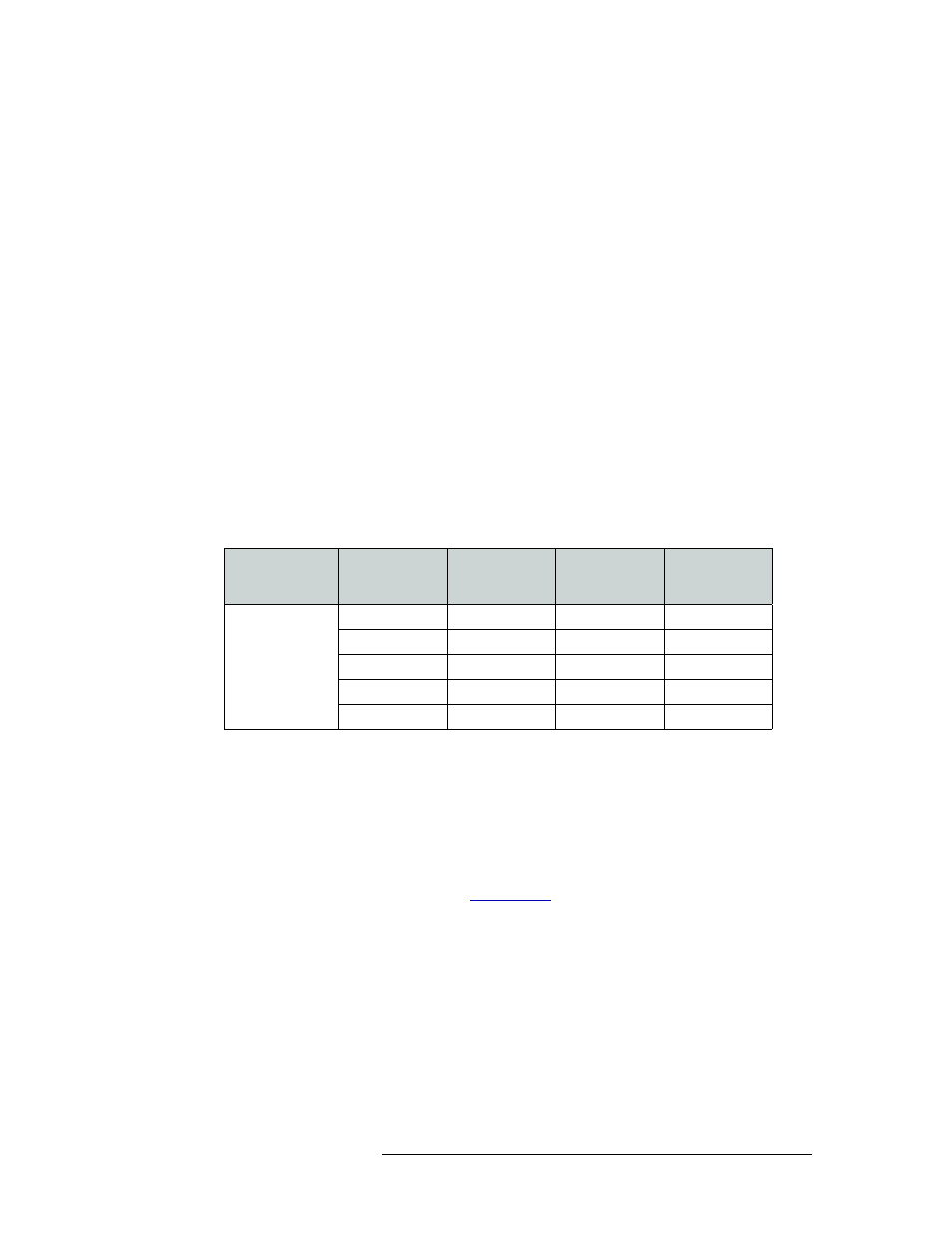
The following lists the different combinations for different incoming sample rates, and the related
connector numbers used on the I/O backplane:
Sample rates between connected router frames can be 48kHz, 96kHz or 192kHz.
Mixing Analog and Digital
The NV7512 frame can mix analog and digital audio signals within a single routing system. For
example, a digital input can be routed to an analog output. Using analog-to-digital and digital-to-
analog convertors on the analog input cards and analog output cards, the router converts analog sig-
nals to digital or digital to analog. (See
on page 20.) This feature can dramatically
lower overall conversion costs when integrating existing analog devices into an existing plant.
Input
1, 5, 9, 13, 17,
21, 25, 29
Input
2, 6, 10, 14, 18,
22, 26, 30
Input
3, 7, 11, 15, 19,
23, 27, 31
Input
4, 8, 12, 16, 20,
24, 28, 32
Sample rate of
incoming signals
for each input.
“X” denotes input
connector not
used.
192
X
X
X
96
X
96
X
96
X
48
48
48
48
96
X
48
48
48
48