Installation – Grass Valley NV7512 v.1.3 User Manual
Page 76
66
Rev 1.3 • 10 Oct 08
2. Installation
Making Diagnostic Connections
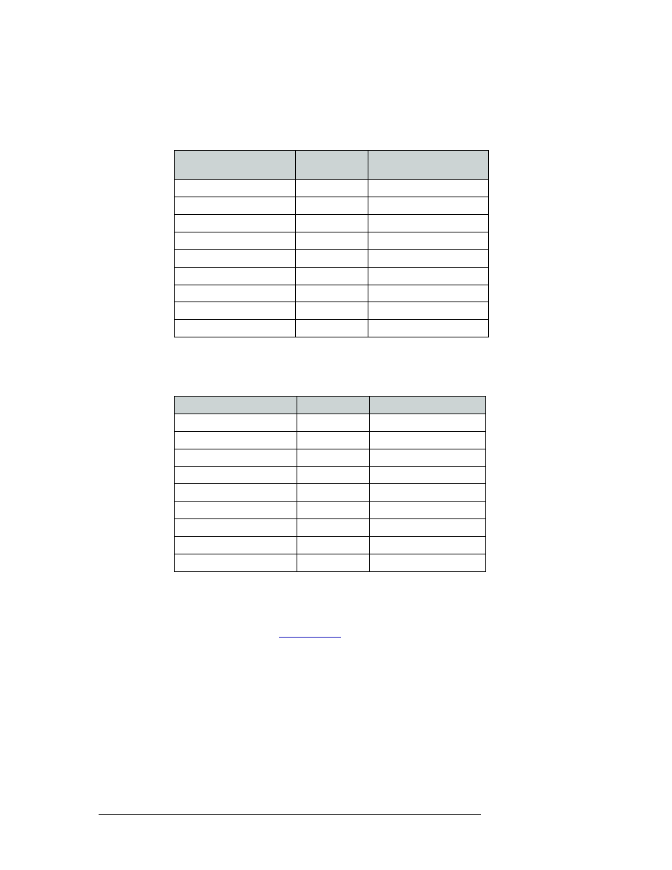
2 Connect to the ‘DIAG’ connection in the ‘PRI CTRL’ section using a DE9 connector and a
serial cable. The ports are set for RS-232:
The following lists the DE9 pin connectors for RS-232:
The DE9 connector can be set for RS-422, but adjustments will need to be made in UniConfig.
For more information, see the UniConfig User’s Guide.
The following lists the DE9 pin connectors for RS-422:
3 Connect the other end of the cable to the hardware running the UniConfig application.
4 If a secondary control card is installed (optional for redundancy), connect to the ‘DIAG’ con-
nection in the ‘SEC CTRL’ section using a DE9 connector and a serial cable as described in
Step 2 and Step 3. (See
Hardware End 9-Pin
Signal
Pins
Router End 9-Pin Signal
DCD
1 ------------1
Ground
RXD
2 ------------2
TXD
TXD
3 ------------3
RXD
DTR
4 ------------4
DSR
Signal Ground
5 ------------5
Signal Ground
DSR
6 ------------6
DTR
RTS
7 ------------7
CTS
CTS
8 ------------8
RTS
Ground
9 ------------9
Ground
Hardware End
Pins
Router End
Ground
1 ------------1
Ground
Rx–
2 ------------2
Tx–
Tx+
3 ------------3
Rx+
Transmit Common
4 ------------4
Receive Common
N/C
5 ------------5
N/C
Receive Common
6 ------------6
Transmit Common
Rx+
7 ------------7
Tx+
Tx–
8 ------------8
Rx–
Ground
9 ------------9
Ground