Analog, Introduction – Grass Valley NV7512 v.1.3 User Manual
Page 33
NV7512 Audio Router • User’s Guide
23
1. Introduction
Active Cards
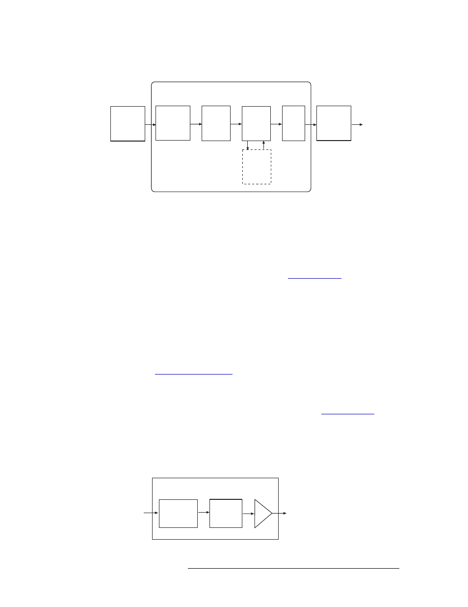
Figure 1-17 shows the signal flow for a MADI synchronous input card.
Figure 1-17. MADI Synchronous Input Card Block Diagram
MADI Asynchronous Sample Rate Converter Sub-Module
MADI signals may contain audio data that is asynchronous to the system clock. To convert the sig-
nals to the same rate, two Sample Rate Converter sub-modules (SM0478) can be installed on the
MADI input card in the SODIMM sockets. A DIP switch on the Sample Rate Converter sub-mod-
ule indicates if the input rate is 1x (32kHz to 50kHz) or 2x (64kHz to 96kHz), and converts all
incoming audio data to 48kHz or 96kHz. If the Sample Rate Converter sub-modules are installed,
the MADI reference connections must be connected. (See
on page 67.) For more
information on acquiring, installing, and setting DIP switches on the Sample Rate Converter sub-
module, contact NVISION.
If the Sample Rate Converter sub-module is not installed and the asynchronous signal is not syn-
chronized to the system reference, the data becomes corrupt.
Analog
The analog input card (EM0418) supports incoming analog signals received through local DB25
connectors. The input card features DIP switches and a jumper that allow gain and mute detection
to be set. (See
on page 87.) In addition, using a separate DIP switch set-
ting the operating level of the card can be set to match the operating level of the facility. For exam-
ple, if the operating level is +24
dBu, the card can be set to +24
dBu. By matching the incoming
signal level, there is less degradation of the signal when it is converted to digital for internal routing
in the router. For information on setting analog input card levels, see
The analog input card can receive up to 16 stereo (32 mono) signals. Each signal is forwarded to an
analog-to-digital converter. The converter converts the signal into a digital signal with a sample rate
of 48kHz for internal routing. The converter then sends the signal to the motherboard and onward
to the crosspoint cards.
Figure 1-16 shows the signal flow for an analog input card.
Figure 1-18. Analog Input Card Block Diagram
Receiver
Transformer
Coupled
Buffer
All Crosspoint
s
AES10
Process-
ing
Module
SRC
Module
Coaxial
Connector
(64)
Mother-
board
MADI Input Card
Local Input
Connectors
(up to 4)
Digital to
Analog
Converter
All
Crosspoints
Input Card
Input and
Gain