Installation, Vac, 50/60, Making power connections – Grass Valley NV7512 v.1.3 User Manual
Page 47: Power connector power supply monitors
NV7512 Audio Router • User’s Guide
37
2. Installation
Making Power Connections
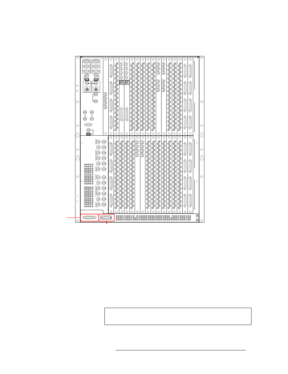
4 Facing the rear of the router, connect the other end of the power supply cable to ‘POWER
INPUT’, as shown in Figure 2-3.
Figure 2-3. Location of Power Supply Monitor Connection
5 Facing the rear of the NV6257, connect one end of the monitor cable (WC0046) to the ‘Power
Supply Monitors’ connection, as shown in Figure 2-2 on page 36.
6 Facing the rear of the router, connect the other end of the monitor cable to ‘POWER SUPPLY
MONITORS’, as shown in Figure 2-3.
7 Facing the rear of the NV6257, connect power cords from an AC power source (90-130/180-
230
VAC, 50/60
Hz) into power connections PS 1 through PS 8, as shown in Figure 2-2 on
page 36. Connect one power cord for each PS6000 power supply module installed (see Step 8).
8 Install the PS6000 power supply modules as follows:
a Facing the front of the NV6257, install the primary PS6000 power supply modules in slots
PS 1 and PS 3, as shown in Figure 2-4 on page 38.
449-480
417-448
385-416 353-384
321-352 289-320
257-288
225-256
193-224
161-192 129-160
97-128
65-96
33-64
1-32
481-512
I
N
P
U
T
S
O
U
T
P
U
T
S
22
22
22
22
22
22
22
22
22
22
22
22
22
22
22
22
22
22
22
22
QUAD MIX
OUTPUT
ANALOG
AUDIO
OUT
10/100BT
2
3
4
QUAD MIX
OUTPUT
1
QUAD MIX
OUTPUT
ANALOG
AUDIO
OUT
10/100BT
2
3
4
QUAD MIX
OUTPUT
1
OUT 1
REF 1 OUT
REF 1 IN
OUT 2
REF 2 OUT
REF 2 IN
OUT 1
REF 1 OUT
REF 1 IN
OUT 2
REF 2 OUT
REF 2 IN
MADI
INPUT
IN 1
REF 1
IN 2
REF 2
MADI
INPUT
Power Connector
Power Supply
Monitors
Note
The NV6257 fans are powered by slot PS 1 or PS 2. A PS6000 power sup-
ply module must be installed in one of these slots.