Redundancy, Fuses, Cooling – Grass Valley NV7512 v.1.3 User Manual
Page 13: Redundancy fuses cooling, Introduction
NV7512 Audio Router • User’s Guide
3
1. Introduction
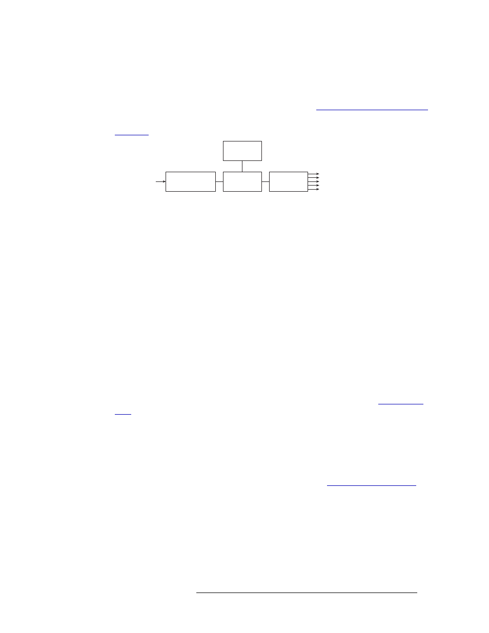
Power Supply
The five regulated outputs are directed to modules in the router where on-board regulators produce
the DC voltages required by the local circuits. Each +48
VDC output powers one of the five green
LEDs and output test points located on the front of each PS6000 power supply module. Under nor-
mal operation, all five LEDs are lit. For more information, see
Module Slots and Rear Connectors
Figure 1-1
shows the power supply architecture.
Figure 1-1. PS6000 Power Supply Module Diagram
Redundancy
The NV6257 can have a maximum of 8 AC power cords connected: up to four primary and four
optional for redundancy, creating a resilient power supply system. Each power cord connected cor-
responds to an installed PS6000 power supply module. Because there are multiple primary power
cords, if one becomes detached or fails, only power to the corresponding individual PS6000 mod-
ule is interrupted. If the optional power cords are connected, there is no interruption in power
should a primary power cord fail.
Fuses
Fuses for AC power inputs are located on the PS6000 power supply modules. When a NV6257 is
ordered, fuses appropriate for the line voltage in use at the country of destination are installed on
the PS6000 power supply modules. Be sure to check the fuse ratings for compliance with specific
requirements in your area. A 7.5A fuse is required for 90-130
VAC applications. For 180-250
VAC
operation, a 3.75A fuse is required.
The fuses are “slow blow” and designed to blow if there is an ongoing power issue, but not if there
is a single, minor spike in the power flow. For information on replacing fuses, see
Cooling
There are four low-speed fans located along the front edge of each PS6000 power supply module.
Each fan pulls a small quantity of air across the internal heat sinks. In addition, the NV6257 has a
single fan that draws air through the power supply chassis. The frame fan is powered by PS6000
power supply modules installed in either slot PS1 or slot PS2 (see
page 35).
Power Sense
and Limiting
AC Input, Fuse,
Rectifiers, and Filter
Power Factor
Correction
+48VDC
Regulators (×5)
+48VDC
Out (×5)
90130VAC or
180250VAC In