Slots and corresponding signal numbers, Bers, see, Slots and corre – Grass Valley NV7512 v.1.3 User Manual
Page 20: Sponding signal numbers, Introduction
10
Rev 1.3 • 10 Oct 08
1. Introduction
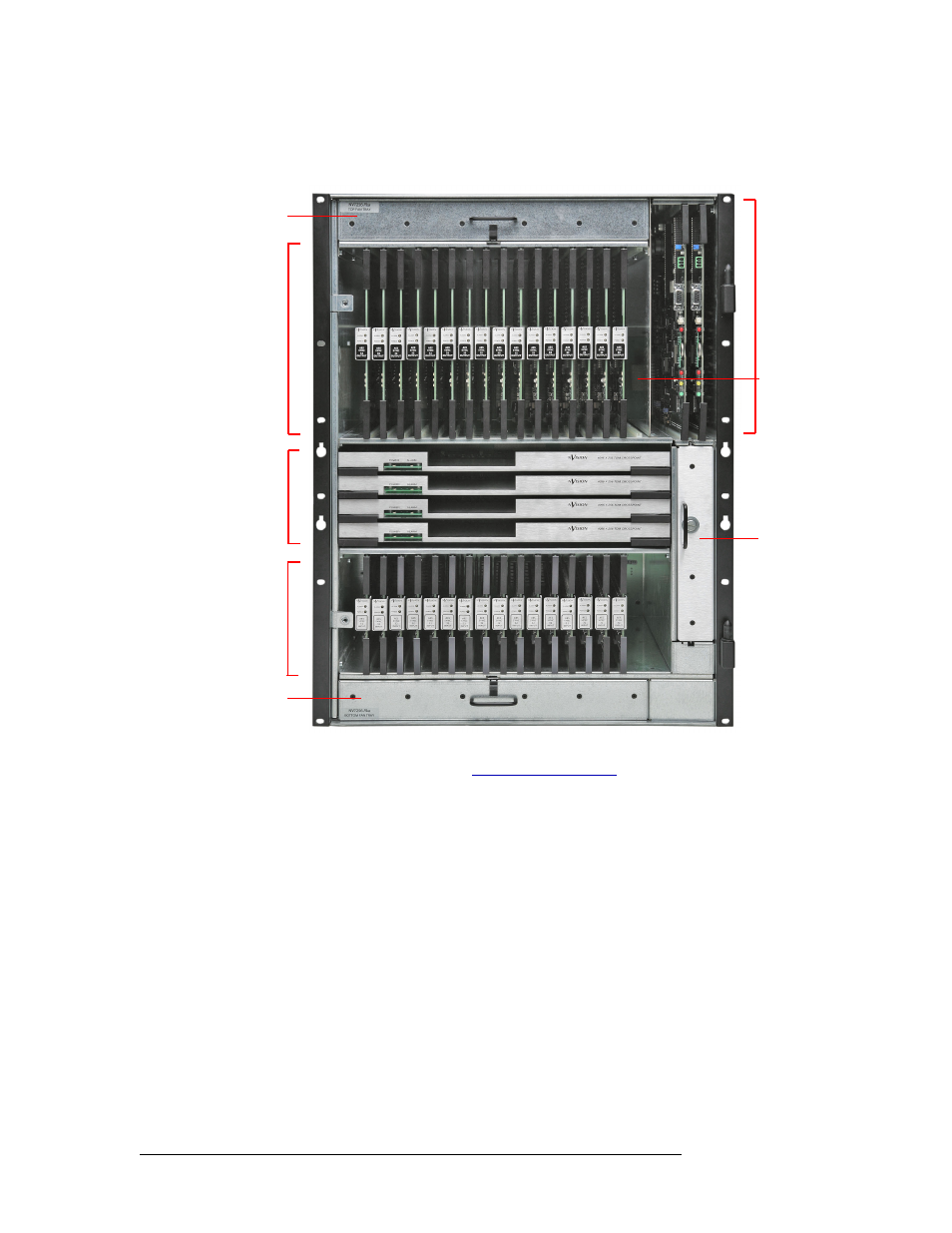
Module Slots and Rear Connectors
Figure 1-3 shows where different cards and the fan trays are located in the frame, as viewed from
the front. The monitor card is optional and not shown as installed.
Figure 1-3. NV7512 Router with Cards Installed, Door Removed (Front View)
For information on installing cards, see
Slots and Corresponding Signal Numbers
The router has 16 slots for input cards and 16 slots for output cards. Slots are numbered 1, 2, and so
on, from left to right, when facing the front of the router. Each input card slot and output card slot,
and the card it holds, receives or distributes signals through coaxial connectors housed on a back-
plane. Each signal is assigned a number that corresponds to the physical input or output connection
up to the maximum number of signals allowed (32). The signal numbers correspond to the slot in
which an input card or output card is installed: Input slot 1 corresponds to inputs 1–32, input slot 2
corresponds to inputs 33-64, and so on, up to 512, as shown in Figure 1-4 on page 11. Output slots
are similarly numbered, such that output slot 1 corresponds to outputs 1–32, output slot 2 corre-
sponds to outputs 33–64, and so on, up to 512, as shown in Figure 1-4 on page 11.
Fan Tray
Output
Cards
(16)
Input
Cards
(16)
Fan Tray
Fan Tray
Cross-
point
Cards
(4)
Control
Cards
(2)
Monitor
Card