10 remove the temporary installation handles, 11 if not already installed, install the fan trays, 13 reinstall the front door – Grass Valley NV7512 v.1.3 User Manual
Page 44: Installation
34
Rev 1.3 • 10 Oct 08
2. Installation
Rack Mount
7 If the router was shipped with the active cards (e.g., circuit boards) and fan trays in the frame,
consider removing them to make the frame lighter for installation. If removing active cards, be
sure to note which card was installed in which slot for later reinstallation.
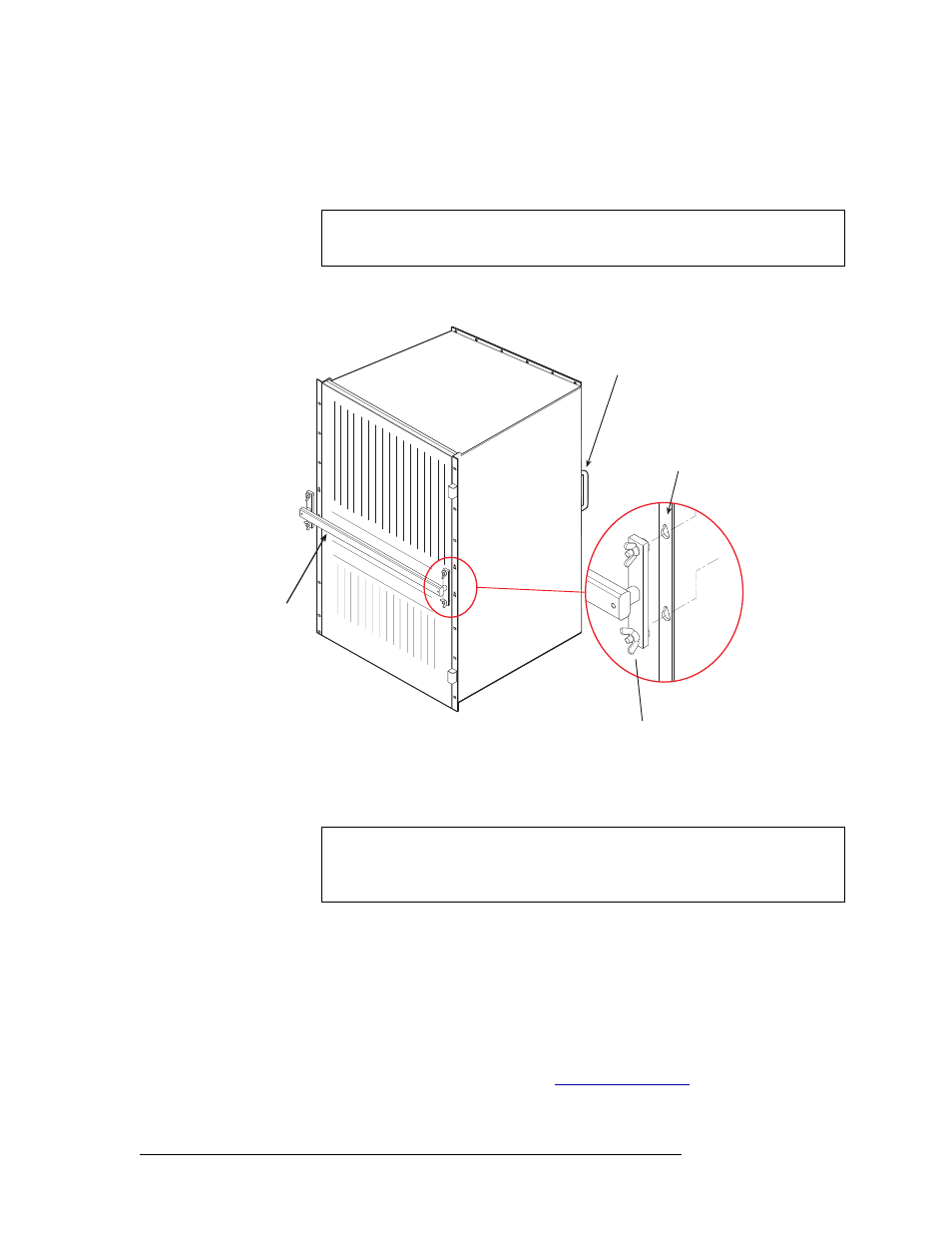
8 Install the temporary installation handle on the front of the frame, as shown in Figure 2-1. The
handle fits into the keyhole-shaped slots. These handles are used to lift the frame into position.
Figure 2-1. Frame Installation Handles, Front and Rear
9 Lift the frame into position and attach the router frame to the front of the rack with the appropri-
ate screws. Be sure to place screws in all frame mounting screw holes.
10 Remove the temporary installation handles.
11 If not already installed, install the fan trays:
Locate the fan trays. There should be three.
Insert fan trays in the fan tray slots, located at the top, right, and bottom when facing the front
of the router frame, as shown in Figure 1-3 on page 10. Top and bottom fan tray are installed
right-side up. The right fan tray is installed with the top of the tray facing left.
12 Reinstall any previously removed active cards (circuit boards). Be sure to install them in the
correct location. For installation instructions, see
13 Reinstall the front door.
Caution
Handle all circuit boards with care. Be sure to use ESD protection and place the
circuit boards in ESD bags or on an ESD surface.
Rear Handle
(one each side)
Frame Slots for
Installation Handle
(two each side)
Wing Nuts
(two each side)
Installation
Handle
NV7256
(front)
Caution
An equipment jack or two people are required to lift and install the router frame.
The router frame is considered too heavy for one person to lift and install in the
rack.