Backplanes, Back, Planes – Grass Valley NV7512 v.1.3 User Manual
Page 22: Introduction
12
Rev 1.3 • 10 Oct 08
1. Introduction
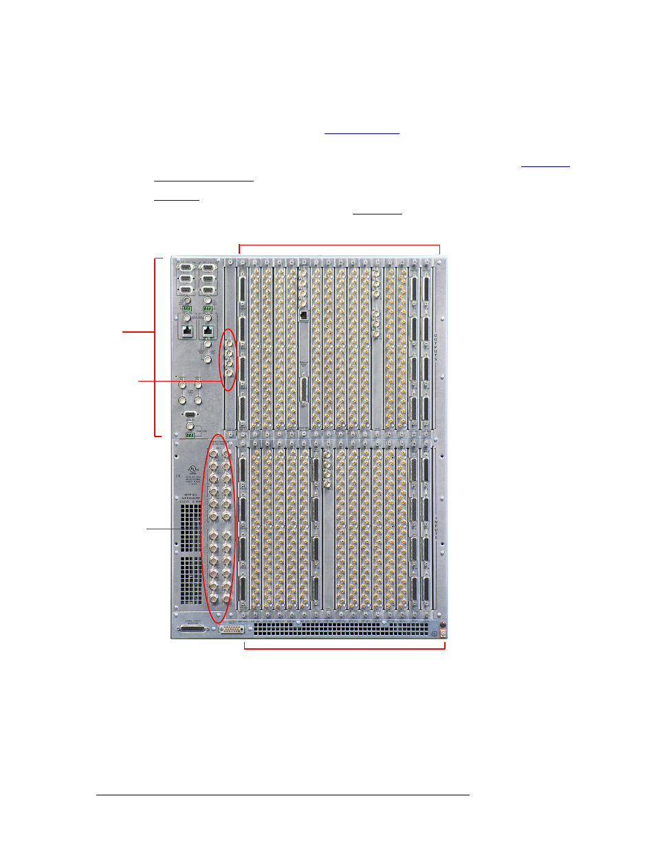
Module Slots and Rear Connectors
connections for system and power functions, as shown in Figure 1-7 on page 15. In the lower
region of the frame, near the left-hand side, are expansion connections used to send signals between
connected NV7512 router frames. (See
Each of the four crosspoint card slots manage up to 128 outputs, or four output cards managing up
to 32 outputs each. For information on crosspoint cards and the signals managed, see
Figure 1-5
shows the rear of the router frame with backplanes installed. Backplanes plug into con-
nectors located on the inner motherboard (see
on page 12). Active cards, shown in
Figure 1-3 on page 10, plug into the same motherboard from the front.
Figure 1-5. NV7512 Router with MADI and AES Backplanes (Rear View)
Backplanes
The NV7512 features rear backplanes that can be inter-mixed in a single router frame. (See
Figure 1-5.) Each backplane contains connectors for receiving or distributing signals. The number
of connectors on a backplane and the type of connector is determined by the signal type.
Output Connectors - Backplanes (16)
Input Connectors - Backplanes (16)
Monitor
Connectors
(4)
System
Connectors
(see
expanded
figure)
Expansion
Connectors
(24)