Connecting multiple routers, Module slots and rear connectors, Front slots – Grass Valley NV7512 v.1.3 User Manual
Page 19: Introduction
NV7512 Audio Router • User’s Guide
9
1. Introduction
Module Slots and Rear Connectors
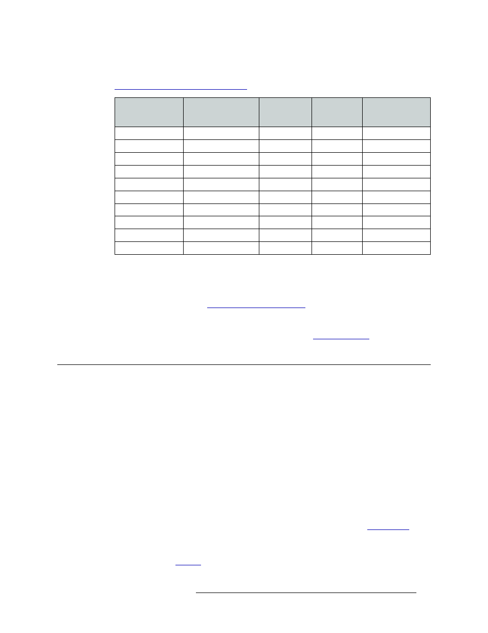
being supported need to be installed. For more information on input and output signal numbers, see
Slots and Corresponding Signal Numbers
Connecting Multiple Routers
Each router can have up to four crosspoint cards installed. When two or more routers are connected
together, the crosspoint cards can route all local inputs plus all inputs received through the signal
expansion connections. (See
on page 53.) If two routers are con-
nected together, each with 512 inputs, the combined signals routed by the router is 1024 inputs. Up
to four NV7512 routers can be connected together to route a maximum of 2048 inputs and 2048
outputs (AES synchronous stereo). For more information, see
Module Slots and Rear Connectors
The NV7512 has slots for input, output, crosspoint, control and monitor cards. Cards are installed
in slots readily accessed through the front of the router frame. The rear of the router is a back plate
into which backplanes housing coaxial connections for receiving and distributing signals are
installed. The back plate also contains connections to system functions, such as a router control sys-
tem, alarms or references.
Front Slots
Figure 1-3 on page 10 shows the front of the NV7512 with the door removed. From this view, the
16 upper bay slots for output cards and 16 lower bay slots for input cards are visible. In the center
of the router are four horizontal slots for crosspoint cards. In the right-hand section of the upper bay
are two more slots for the primary and secondary (optional for redundancy) control cards. A slot for
the monitor card is also located in the right-hand section of the upper bay, between the output card
slots and the control card slots. For more information on each type of card, see
A fan tray is located at the top, bottom, and right side of the router chassis. For more information on
frame cooling, see
Total Number of
Inputs x Outputs
Output Signal
Numbers
Total Number
of Output
Cards
Total Number
of Crosspoint
Cards
Crosspoint Card
Slot
512 × 512
1–512
16
4
A, B, C, D
512 × 384
1–384
12
3
A, B, C
512 × 384
129–512
12
3
B, C, D
512 × 384
1–128, 257–512
12
3
A, C, D
512 × 256
1–256
8
2
A, B
512 × 256
129–384
8
2
B, C
512 × 256
257–512
8
2
C, D
512 × 256
1–128, 257–384
8
2
A, C
512 × 128
129–256
4
1
B
512 × 128
385–512
4
1
D