Gsc node bus router control connections, Gsc node, Bus router control connections – Grass Valley NV7512 v.1.3 User Manual
Page 70: Installation
60
Rev 1.3 • 10 Oct 08
2. Installation
Making Router Control System Connections
How to make an Ethernet connection to the router control system
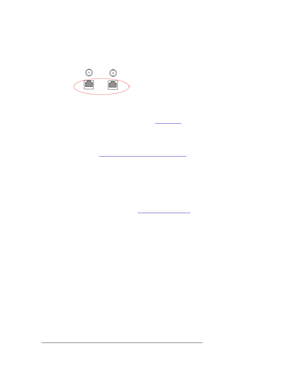
1 Locate the Ethernet connections on the rear of the router, as shown in Figure 2-20. Ethernet
control connections are labeled ‘10/100baseT’.
Figure 2-20. Ethernet Connections to Router Control System (Rear View)
2 Connect to either ‘10/100baseT’ connection using a RJ45 connector and Cat5, or better, cable.
3 Connect the other end of the Ethernet cable to the primary router control system PC.
4 If a secondary (optional for redundancy; see
on page 20) control card is installed,
connect to the remaining ‘10/100 BASE T’ connection using a RJ45 connector and Cat5, or bet-
ter, cable
5 Connect the other end of the second Ethernet cable to the redundant router control system PC.
6 If two NV7512 routers are being connected together, connect the control system expansion con-
nections. See
Router Control System Expansion Connections
Or
If the NV7512 is being used as a standalone router, install 50
Ω BNC terminators on the control
system expansion connections.
GSC Node Bus Router Control Connections
Some third-party router control systems require a GSC Node Bus connection to connect the router
to the router control system. The NV7512 has one GSC Node Bus connection, labeled ‘NODE
BUS’, which is shared by both the primary and secondary control cards. For a detailed description
of the GSC Node Bus connection, see
To use the GSC Node Bus connection, an optional module must be installed on each control card.
For details, contact NVISION.
The GSC Node Bus connection uses 75
Ω BNC connectors and coaxial cable.
Ethernet
Connections
to Control
System
10 BASE 2
10/100 BASE T
10 BASE 2
10/100 BASE T
COMMON
TO
PRI & SEC