Command/message block structure, Byte count, Effects address byte – Grass Valley 2200 User Manual
Page 19: Command/message block structure -5, Byte count -5 effects address byte -5
2-5
Command/Message Block Structure
Command/Message Block Structure
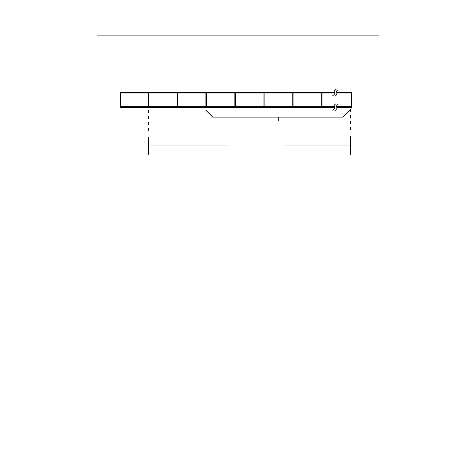
In the Selected state, the Editor Interface receives command/message blocks that
direct switcher operations. The basic message structure is shown in Figure 2-4.
The maximum length of a message is 255 bytes plus the byte count byte. At a baud
rate of 38,400, the maximum length command/message takes more than 4 Þelds to
complete.
The Editor Interface can handle data continuously, receiving a contiguous stream
of command/message blocks. Such an ability enables multiple switcher
operations to be performed without constant cycling through the break/address
sequence. Responses (handshakes or read data) are returned in the same order as
the command/message blocks are received.
Byte Count
The command/message block can range in size from two to 256 bytes. The Þrst
byte of the block contains the byte count. A byte count consists of the total number
of subsequent bytes in the block; valid byte count values range from 01H to FFH
(1 to 255). After receiving a valid byte count (01H to FFH) and the proper number
of data bytes (1 to 255), the Model 3000 executes the command.
Effects Address Byte
The second byte of the command/message block is the effects address byte,
typically referred to as EX. This byte identiÞes the desired Òeffect bankÓ within the
switcher where the associated command will go. Valid Effects Addresses for each
command are speciÞed in Section 3.
Figure 2-4. Message Structure
Message Bytes
Effects
Addr. Byte
Command
Code Byte
Byte Count
Byte
Maximum Size
255 Bytes
0350-09