Model 2200/4000, Communication standard, Termination – Grass Valley 2200 User Manual
Page 12: Model 2200/4000 -4, Communication standard -4 termination -4
1-4
Section 1 Ð Introduction
Model 2200/4000
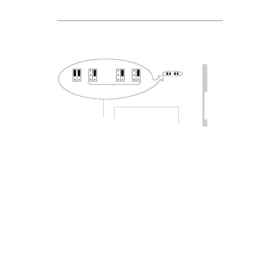
For the Model 2200 or Model 4000, the EDITOR port jumpers are located on the
Control Processor II module (064806) as shown in Figure 1-2. Jumper J15 sets the
communication standard (RS-232 or RS-422); Jumpers J16, J17, and J18 set the
EDITOR port termination (terminated or not terminated).
Communication Standard
For
RS-422
, set the two jumpers of J15 to the upper (RS422) position as shown
in Figure 1-2. This connects pins 1 and 3 together and pins 2 and 4 together.
For
RS-232
set the two jumpers of J15 to the lower (RS232) position. This
connects pins 3 and 5 together and pins 4 and 6 together.
Termination
Set jumpers J16, J17, and J18 to either the upper (terminated) or lower (not
terminated) position, depending upon the requirements of your system. All
three of these jumpers should be set to the same position (all up or all down).
There is only one jumper for each of these jumper blocks.
If J15 is set for RS-232, Jumpers J16 through J18 have no effect.
Figure 1-2. EDITOR Port Jumper Settings on Model 4000
(shown set for RS-422, terminated)
M/E 2 Processor
Mezzanine Board
(068916)
J16
1
5
2
6
1
5
2
6
1
5
2
6
1
5
2
6
J15
SERIAL COMMUNICATION
TERMINATION SELECT
EDITOR
RS422/RS232
SELECT
J18
J17
Control
Processor II
Module
(064806)
rear
edge
connector
0350-12