To name inputs and outputs, I/o config web page – Grass Valley Kameleon HD Multi-Function Modules v.2.1.0 User Manual
Page 37
Kameleon HD Instruction Manual
37
Initial Configuration Process Overview
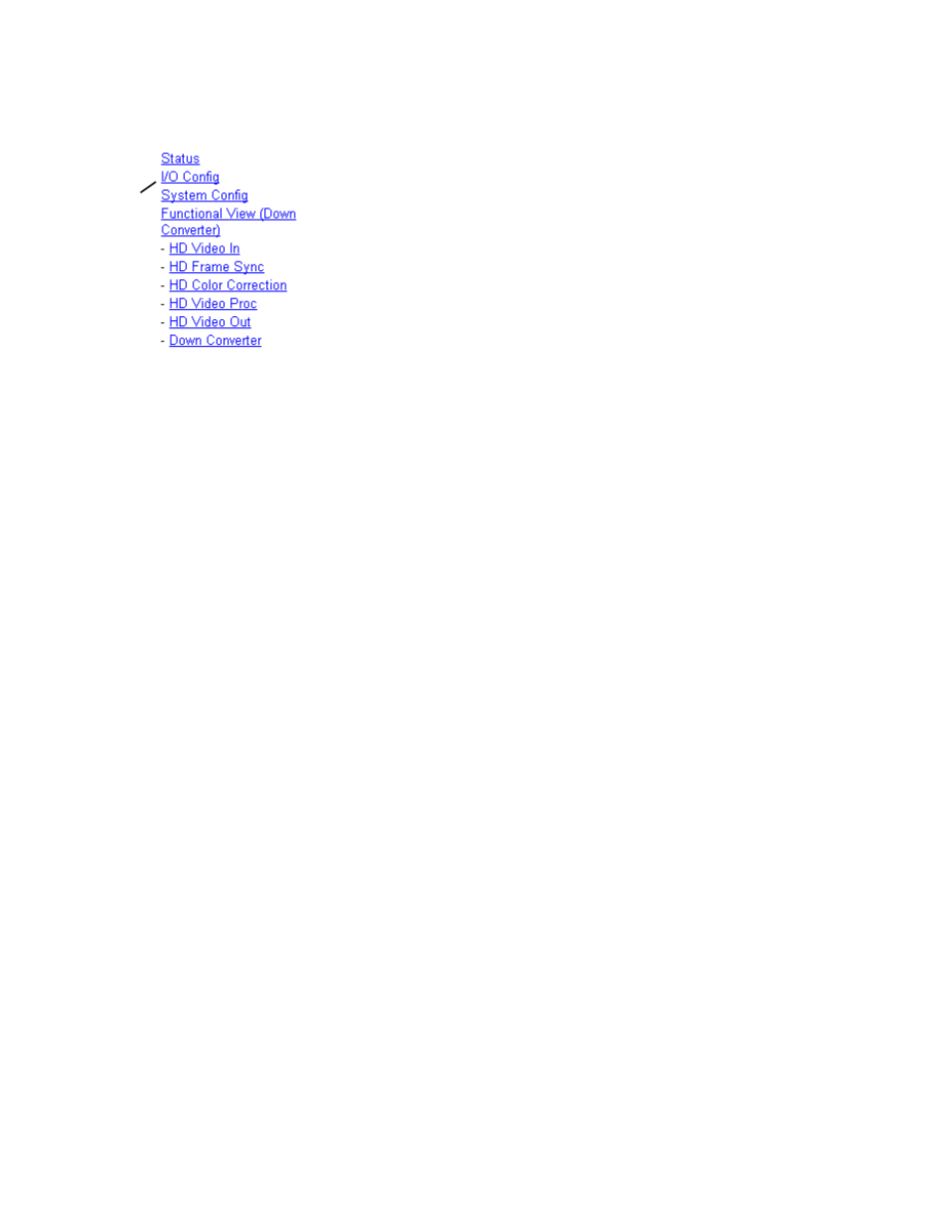
I/O Config Web Page
Use the I/O Config web page to:
•
View a graphical overview of the rear module connectors,
•
See signal status of inputs, and
•
Assign easily recognizable signal names that will help later in the con-
figuration process.
An overall description of the I/O web pages is provided below. Refer to
KAM-HD-FS I/O Config Web Pages on page 38
KAM-HDD-PA/KAM-HDD-FS/KAM-HDD I/O Config Web Pages on page 40
for specific illustrations of the possible I/O Config web pages for each
model type and system configuration.
•
Header Row
– The top header row provides the connector hardware
physical label (J#) and the dedicated signal type for the connector. This
information is determined by the settings of the System Configuration
web page and the module type (refer to the
).
•
Connector
– The connector row illustrates connector types provided for
each port.
•
I
nput/Output Mode
– the I/O mode is static read-only based on the type of
module and the settings made on the System Configuration web page.
•
Signal Naming
– enter a signal name (up to 12 characters) for each opera-
tional input/output. The name will be used to identify the signal in
other configuration web pages. Factory default names for all models
are shown in
.
•
Status Boxes
– as shown in the Legend at the bottom of the I/O Config
web page, each connector is monitored and status reported with the fol-
lowing color code:
•
Green = Pass – signal is present.
•
Yellow = Warning – signal is absent, has errors, or is misconfigured.
•
Light gray = connector is not monitored.
•
Dark gray = connector is unused.
Use
this
link