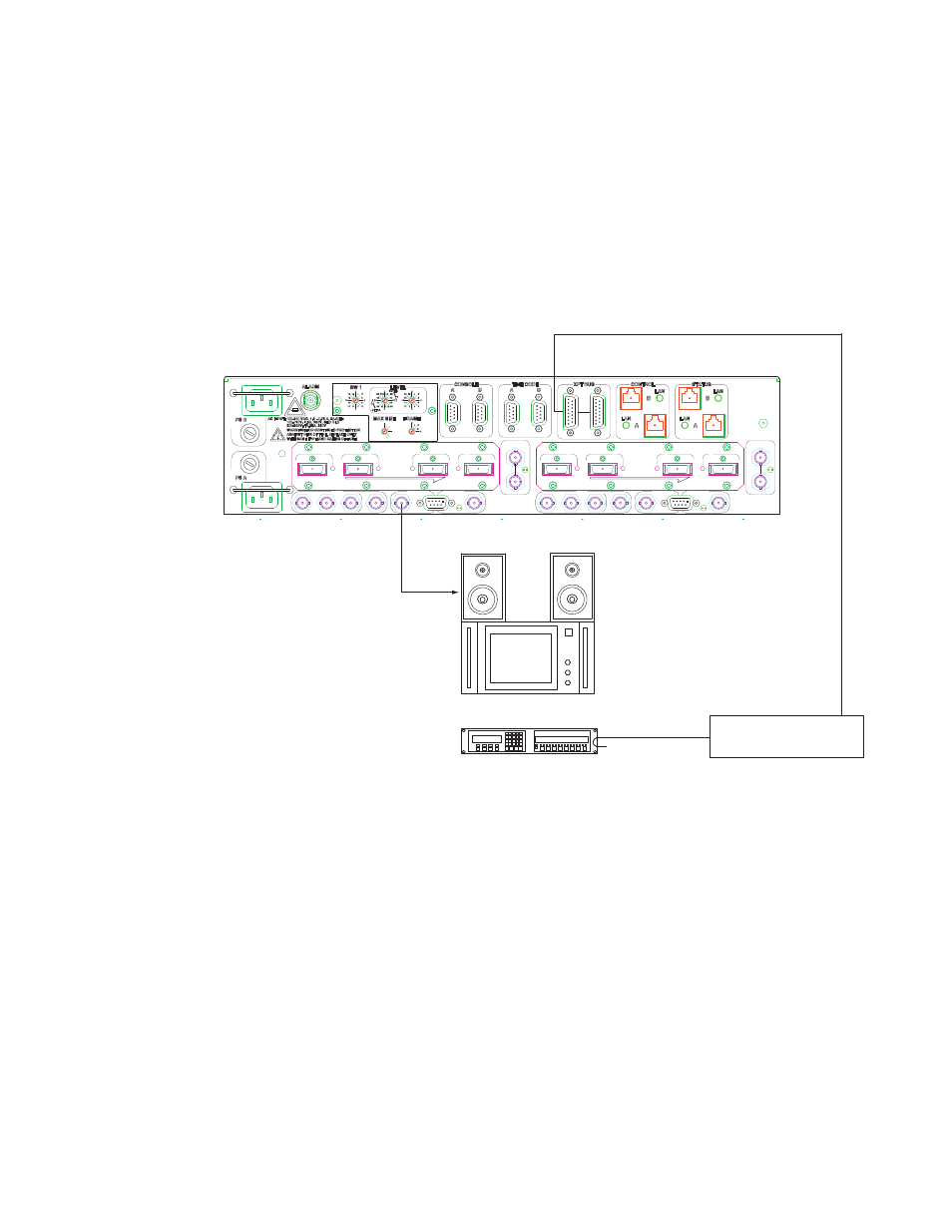
Output monitoring, Figure 42. example of output monitor connection, Jupiter control system switcher control panel – Grass Valley Apex v.2.0 User Manual
Page 97: Crosspoint bus mpk bus monitoring station
APEX — Installation and Service Manual
99
Output Monitoring
Output Monitoring
Note
Output monitoring is a standard Apex system feature.
Output monitoring allows verification of switcher performance without
interrupting normal operations. A separate internal switching system is
used to switch the selected output signal to the Output Monitor connector.
See
Figure 42. Example of Output Monitor Connection
Using a standard system control panel, the operator picks an output as
usual—in this case, the Output Monitor. (The physical number of the
Output Monitor connector is determined by the Max Size switch setting
plus 1—see Max Size Switch
.) The operator then selects an input,
but this input is actually one of the switcher outputs.
Two connector sets are provided on each chassis: OP MON A, which corre-
sponds to the A Matrix board; and OP MON B, which corresponds to the
optional B (secondary) Matrix board. Within each set are two connectors: a
BNC type for 75 Ohm cabling, and a 9-pin D female type for 110 Ohm
cabling. Pinouts for the D connector are shown in
Note that some pins on this connector are used for 110 Ohm AES Reference
cabling. The signal selected by the control system for monitoring is always
present on both the BNC and the D connectors.
Jupiter Control System
Switcher Control Panel
AES REF B
HIGHEST
A
MC A
LOWEST
OUT
IN
OUT
OP MON A
AES REF A
HIGHEST
2
1
P
X
E
4
3
EXPANSION
B
OUT
OUT
MC B
LOWEST
IN
OP MON B
P
E
X
VID REF A
1
2
EXPANSION
3
4
VID REF B
1536
1792
2048
1280
1024
768
512
256
Crosspoint bus
MPK bus
Monitoring Station