Grass Valley Apex v.2.0 User Manual
Page 76
78
APEX — Installation and Service Manual
Section 3 — Installation
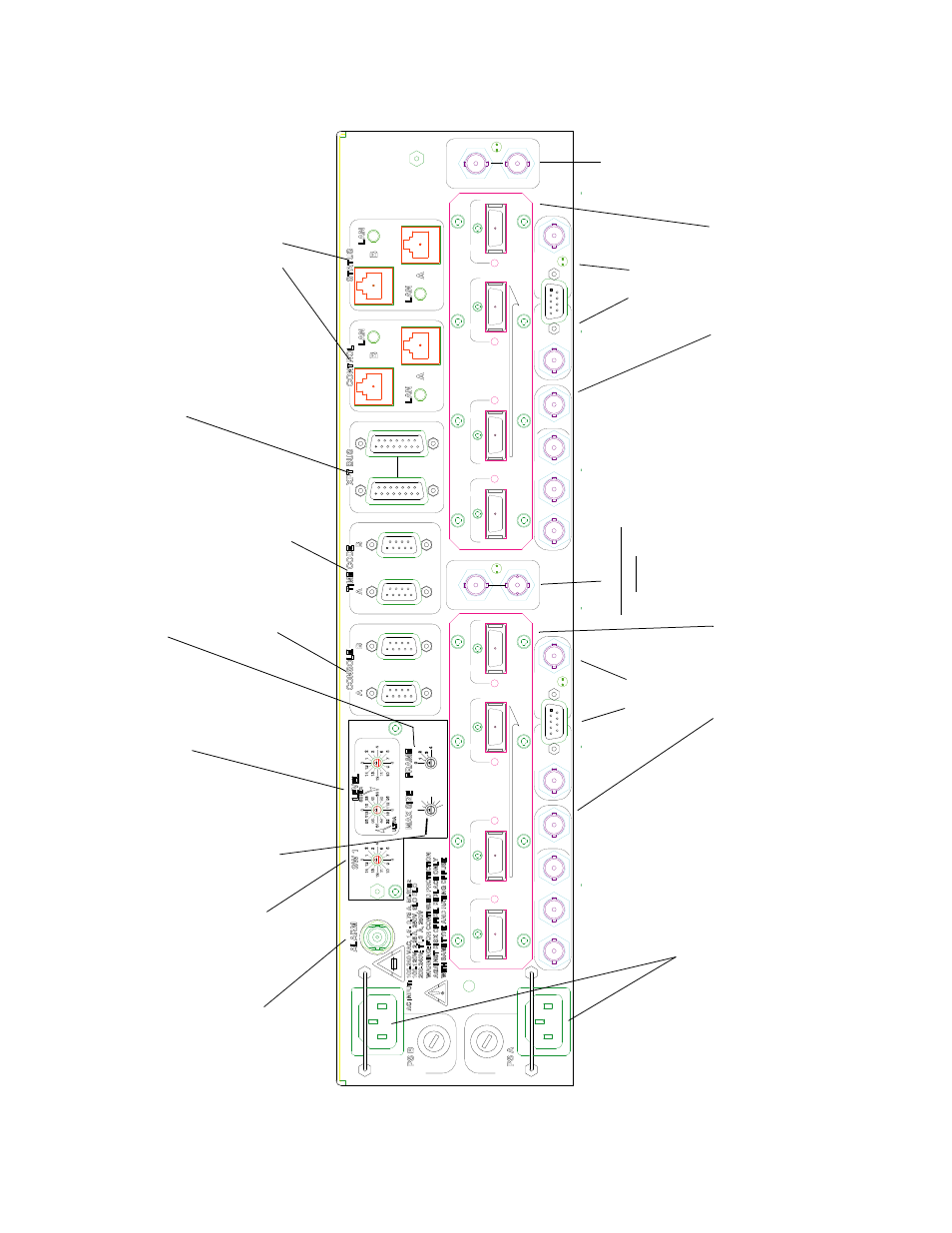
Figure 28. Auxiliary Panel Overview
AES REF B
HIGHEST
A
MC A
LOWEST
OUT
IN
OUT
OP MON A
AES REF A
HIGHEST
2
1
P
X
E
4
3
EXPANSION
B
OUT
OUT
MC B
LOWEST
IN
OP MON B
P
E X
VID REF A
1
2
EXPANSION
3
4
VID REF B
1536
1792
2048
1280
1024
768
512
256
Cr
osspoin
t b
u
s co
nn
ecti
on to
Jupiter
VM/CM
contr
o
lle
r or
to
Tr
inix vide
o r
o
uter
. See
.
Also us
ed for
in
dir
ect connection
to
E
n
co
re
. See
.
Re
fer
e
n
ce
connec
tions
-
see
.
Exp
a
n
si
on
connec
tions
-
see
.
Monitor
connections
- s
ee
Alar
m conn
ector
(S
M
P
TE standar
d
26
9M-
1
9
99)
Not used
Factor
y use
Po
wer
inpu
ts
100
to
2
40
V,
50-
60
H
z
Fr
ame
n
u
m
ber
.
Set to z
ero
for single-
chassis
sy
stems.
For multi-
cha
ssis
sys
tems
,
se
e
.
Physical level number
used by cont
rol s
ystem.
For Jupiter
,
see
.
For Encore, see
.
Max size
-
Sta
n
dard Ape
x
sy
stem size
se
le
ct
. S
ee
.
SW1
-
Apex Plus
syste
m
size
select. See
.
Not pres
ent
ly
use
d
Master
Clock
an
d
InfiniBand
®
conn
ecti
ons to
B
M
atr
ix
bo
ar
d
Master
Clock
and
InfiniBand
®
co
nn
ecti
ons to “
A
” Matrix
b
o
ard
Ou
tput Mo
nitor
A
Vid
eo
Ref
e
re
n
ce
Input A
Output Monitor
B
Vid
eo
Re
fe
re
nc
e
Input B