Grass Valley Apex v.2.0 User Manual
Page 85
APEX — Installation and Service Manual
87
Expanded (Multi-Chassis) Systems
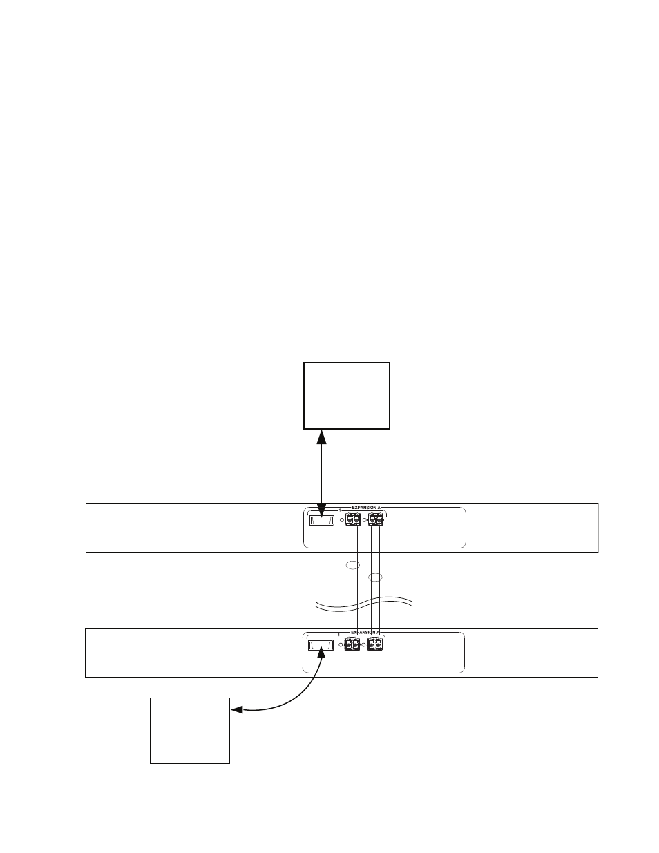
Cabling
shows the cabling details between a remote chassis (Chassis 0)
and a local chassis (Chassis 1). Each chassis is connected to an adjacent
Fiber Extender using an InfiniBand cable. The extenders are connected
using two fiber optic cables, each of which is actually a pair of cables. In this
case, a total of four transceivers are installed, i.e., two transceivers in each
Fiber Extender. Each transceiver is installed label up in the appropriate slot
on the rear panel by sliding the transceiver inward until it locks in place.
The protective black plug is then removed to allow insertion of the fiber
cable.
Note that the protective white covers must be removed from the cables
before they can be connected. To remove the covers, press the blue tab
marked B and A. The wire locking bail on the transceiver must be in the up
position when the connector is inserted.
Redundant (Expansion B) cables are not shown in this example but are con-
nected in a similar manner.
Figure 35. Example of Connections Between Local and Remote Chassis
Chassis 0
Infiniband cable
Infiniband cable
Remote Fiber Extemder
Fiber optic cable pair
Fiber optic cable pair
1
Inputs 1-256
Expansion connector
5 km max.
1
Expansion
connector
Chassis 1
Inputs 257-512
Local Fiber Extemder