Figure 52 on, Level – Grass Valley Apex v.2.0 User Manual
Page 109
APEX — Installation and Service Manual
111
Encore Control
3.
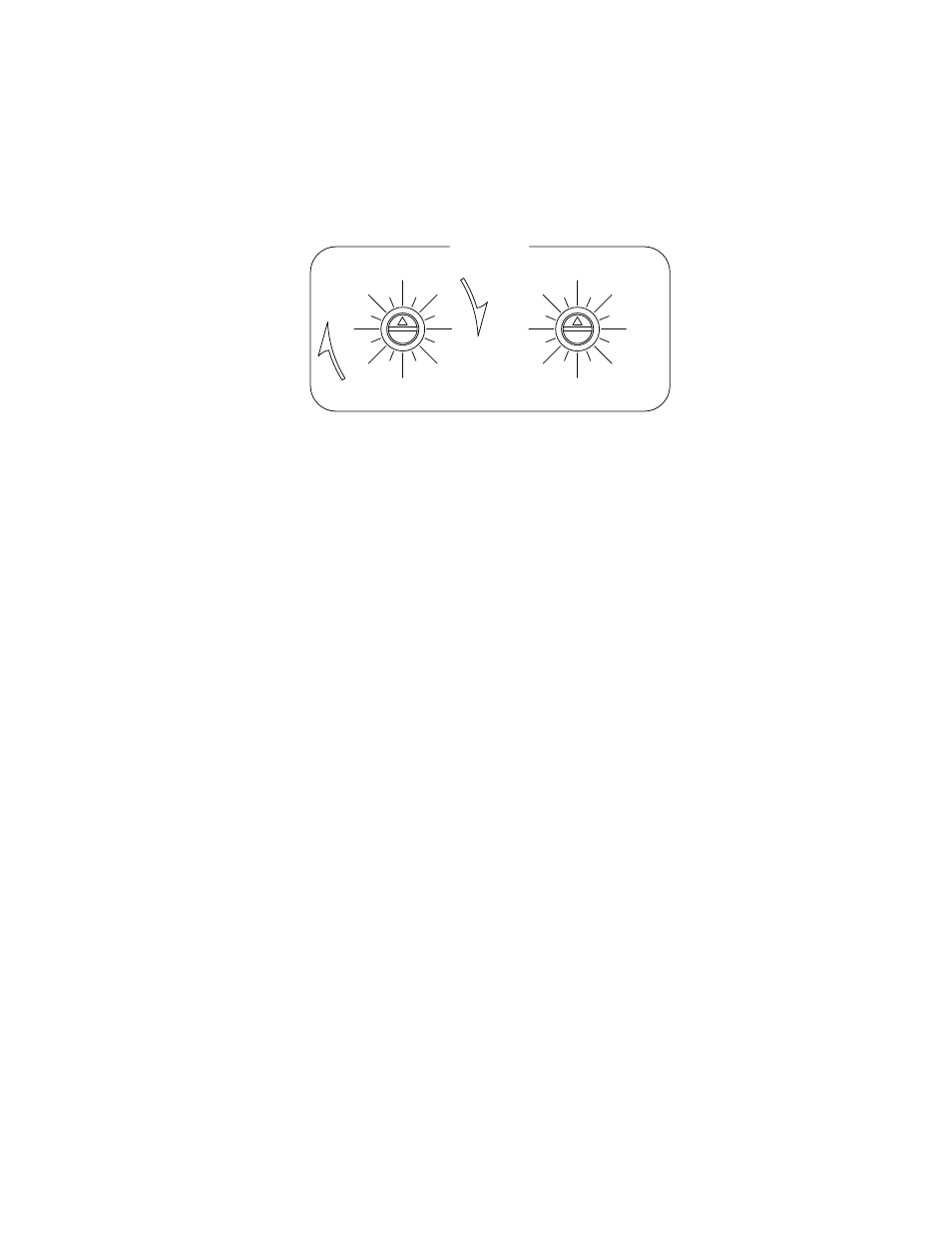
Set Level switches:
Two back-panel rotary switches are used to set the level address of the
router. See
Figure 52. Level Switch Illustration
For Encore control,
Ultra
Crosspoint bus settings must be used. The
left-hand switch is turned to the appropriate most significant bit on the
Ultra
side of the switch; the least significant bit is set on the right switch.
For example, to set the switcher level at
32
(the factory default for serial
digital audio) the left switch would be set at
Ultra 32
and the right switch
set to
0
.
4.
Connect the Status LAN as required. See
Refer to the Encore documentation for control system configuration
details.
As described on S34-1/2 – Stereo/Mono Mode Selection
normally set for two-level stereo operation; this allows for stereo mode
switching such as mix, reverse, etc. In this mode the Apex boards are
programmed so that the right channel is always 4 physical level
numbers higher than the left channel. In the case of Encore control, only
one level number is identified during software configuration (i.e., the
number selected during
above) and stereo switching is normally
selected. The physical level number of the right channel (e.g., 36) must
not be used by any other router controlled by the Encore system.
LEVEL
SUPER
ULTRA
0
0
0
1
2
3
4
5
6
7
8
9
10
11
12
13
14 15
16
16
32
32
48
48
64
64
80
80
96
96
112
112