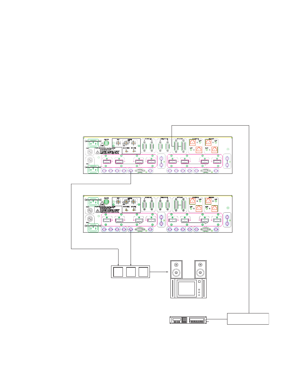
Multi-frame systems, Figure 20. multi-frame output monitor connections, Crosspoint bus mpk bus – Grass Valley Apex v.2.0 User Manual
Page 53
APEX — Installation and Service Manual
55
Facility Interface
The signal selected by the control system for monitoring is always present
on both the BNC and the D connectors.
Multi-frame Systems
On multi-frame systems, each frame is monitored separately. For example,
in a 512 x 512 (2-frame) system, outputs 1-256 are monitored using the OP
MON connector(s) on Frame 0; outputs 257-512 are monitored using the OP
MON connector(s) on Frame 1. See
.
Note
For redundant Matrix board systems, note that the same signal will be
present on the A and B connector sets.
Figure 20. Multi-frame Output Monitor Connections
Monitoring Station
Jupiter Control System
Switcher Control Panel
AES REF B
HIGHEST
A
MC A
LOW EST
OUT
IN
OUT
OP MON A
AES REF A
HIGHEST
2
1
P
X
E
4
3
EXPANSION
B
OUT
OUT
MC B
LOW EST
IN
OP MON B
P
E
X
VID REF A
1
2
EXPANSION
3
4
VID REF B
1536
1792
2048
1280
1024
768
512
256
AES REF B
HIGHEST
A
MC A
LOW EST
OUT
IN
OUT
OP MON A
AES REF A
HIGHEST
2
1
P
X
E
4
3
EXPANSION
B
OUT
OUT
MC B
LOW EST
IN
OP MON B
P
E
X
VID REF A
1
2
EXPANSION
3
4
VID REF B
1536
1792
2048
1280
1024
768
512
256
AES REF B
HIGHEST
A
MC A
LOW EST
OUT
IN
OUT
OP MON A
AES REF A
HIGHEST
2
1
P
X
E
4
3
EXPANSION
B
OUT
OUT
MC B
LOW EST
IN
OP MON B
P
E
X
VID REF A
1
2
EXPANSION
3
4
VID REF B
1536
1792
2048
1280
1024
768
512
256
Crosspoint bus
MPK bus
257-
512
1-
256
Suggested audio switch
Frame 0 - outputs 1 - 256
Frame 1 - outputs 257 - 512