Grass Valley Apex v.2.0 User Manual
Page 103
APEX — Installation and Service Manual
105
Jupiter Control
1.
Install the CC-2010 Matrix (Crosspoint bus) cable.
Interconnection from a Jupiter VM-3000 or CM-4000 control board is
via Crosspoint bus cable, which can be supplied in 3, 10, 25, or 50 foot
lengths.
In multi-frame systems, the Crosspoint bus is connected only to the
chassis containing the CX-34000 Control Crosspoint board(s).
The CC-2010 is a 10-conductor (plus ground) cable. Ready-made cables,
with installed 15-pin D male connectors, are available from Thomson
Grass Valley; see the
section.
All rear-panel Crosspoint bus connectors are 15-pin D, female.
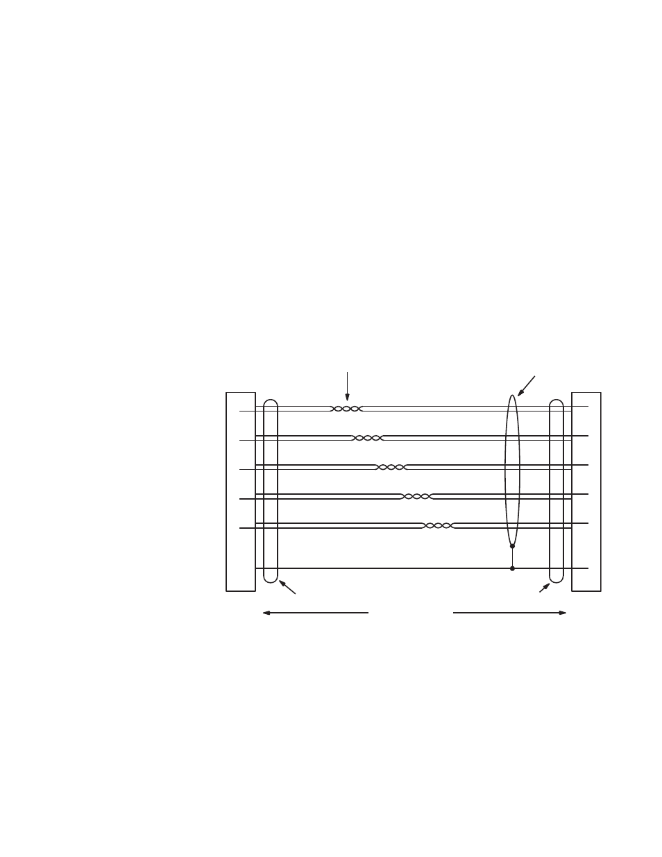
For those who wish to prepare their own Crosspoint cables, pinouts are
shown in
below. The cable itself should be Belden 9505 or
equivalent. (This diagram references Assembly CC-2010 Matrix cable,
drawing number 01-032707-TAB.) Details concerning ferrite cores are
given in
.
Figure 48. Crosspoint Cable Wiring (CC-2010)
1
1
8
P1
DB15P
(male)
Shield (drain)
P2
DB15P
(male)
Red
9
Black
2
Yellow
10
Black
3
Green
11
Black
4
Blue
12
Black
5
White
13
Black
8
2
3
4
5
9
10
11
12
13
Twisted pairs
50 ft ( 15.2 m) max
Ferrite core
Ferrite core
Shield
Red
Black
Yellow
Black
Green
Black
Blue
Black
White
Black
Reset
Data
Clock
Take
Confirm
Ground