Grass Valley Apex v.2.0 User Manual
Page 36
38
APEX — Installation and Service Manual
Section 2 — Planning Guide
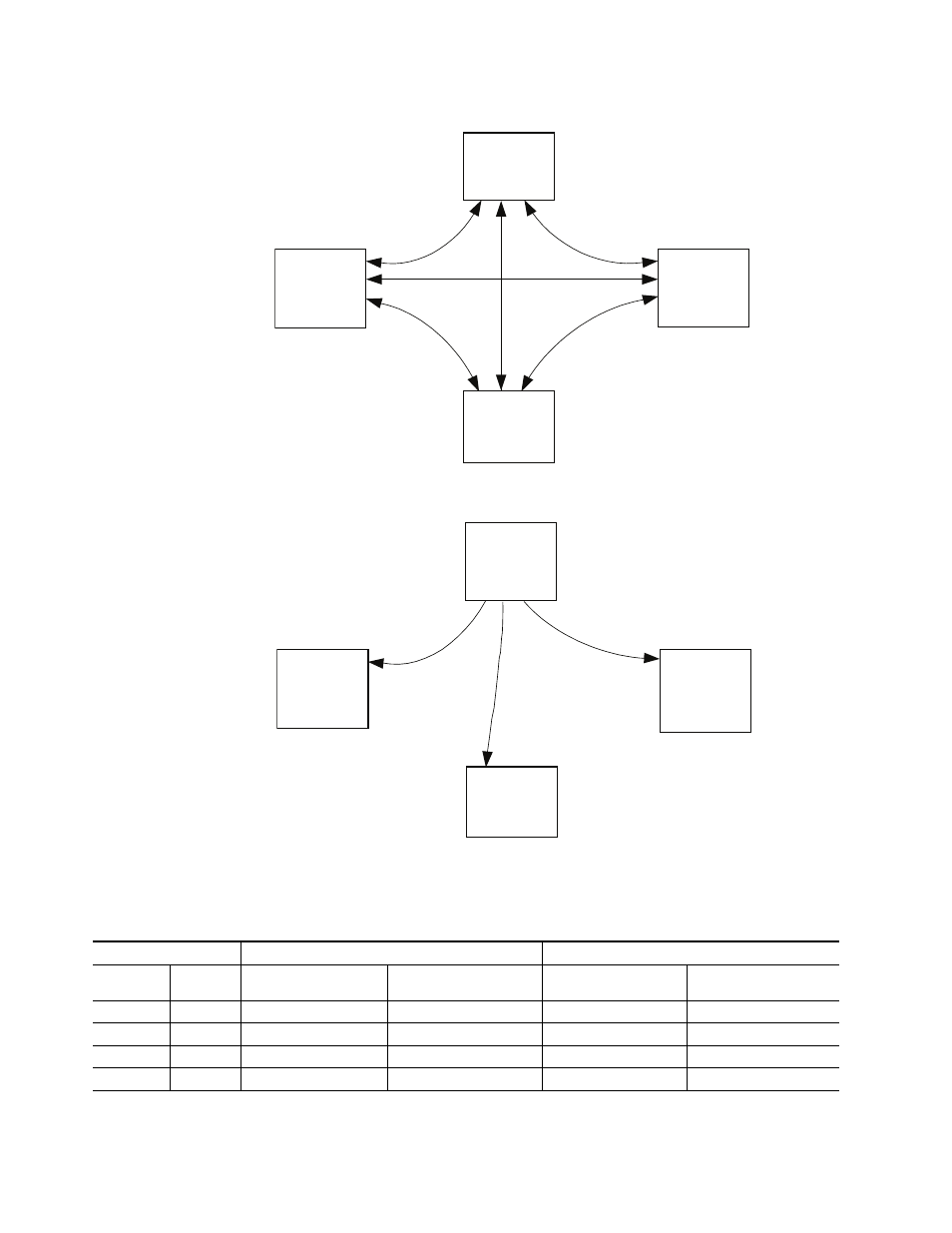
Figure 6. Standard Apex Expansion InfiniBand Cabling (optional redundant cables not shown)
Figure 7. Standard Apex Expansion Master Clock Cabling (optional redundant cables not shown)
Table 1. Standard Apex InfiniBand and Master Clock Cable Requirements
InfiniBand cables needed
Master Clock cables needed
Switcher size
# of Chassis
Non-redundant
(1 Matrix board per chassis)
Redundant
(2 Matrix boards per chassis)
Non-redundant
(1 Matrix board per chassis)
Redundant
(2 Matrix boards per chassis)
256 x 256
1
0
0
0
0
512 x 512
2
1
2
1
2
768 x 768
3
3
6
2
4
1024 x 1024
4
6
12
3
6
Chassis 0
1
2
3
4
Inputs 1-256
Expansion connector
2
1
4
3
Chassis 2
Inputs 513-768
Expansion connector
1
4
3
2
Expansion
connector
Chassis 1
Inputs 257-512
1
2
3
4
Expansion
connector
Chassis 3
Inputs 769-1024
1024 x 1024
Chassis 0
Out Out Out In
Inputs 1-256
In
Out Out Out
Chassis 2
Inputs 513-768
In
Out
Out
Out
Out
Out
Out
In
Chassis 1
Inputs 257-512
Chassis 3
Inputs 769-1024
1024 x 1024