Alarm system – Grass Valley Apex v.2.0 User Manual
Page 59
APEX — Installation and Service Manual
61
Alarm System
Alarm System
All major components (except the fan module) include a local alarm LED.
Fan failure is indicated by the Fan A and Fan B Alarm LEDs on the
MX-34000 Matrix board. (For more information about these and other
LEDs, see Section 4-Section.)
The master alarm indicator is an LED on the front panel (Power/Alarm)
where green indicates normal operation and red indicates an alarm condi-
tion.
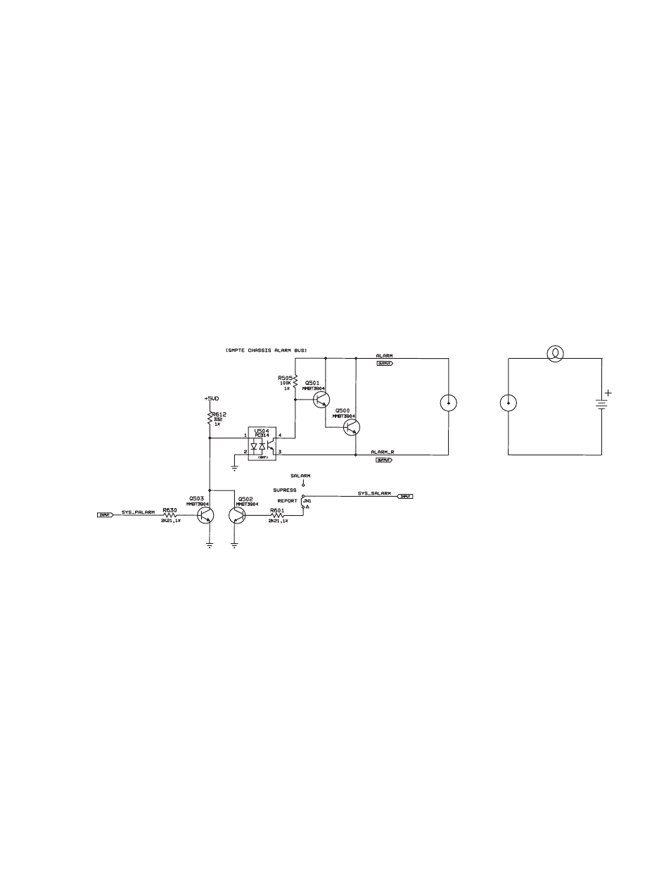
The rear panel Alarm BNC operates according to SMPTE standard
269M-1999. When an alarm is asserted, the circuit that is associated with the
Alarm connector will present low impedance to a customer-provided
external current source. See
for an example of a rear panel master
alarm circuit (left) and an example of a customer-supplied indicator circuit
(right).
Figure 23. Rear Panel Master Alarm Circuit and Customer Example
EXTERNAL CIRCUIT
(EXAMPLE)
NOT TO EXCEED
24 VDC @ 20 mA
REAR PANEL BNC