Electrical inputs, Electrical outputs, Fiber optic outputs – Grass Valley 8943CF User Manual
Page 24
24
8943CF — Instruction Manual
Installation
Electrical Inputs
Connect a signal conforming to the to the specifications given in
to the coax inputs for Channel 1 -4 as labeled on the rear of the
8943CF-R module.
Electrical Outputs
There are four electrical coax video outputs corresponding to Channel 1-4
as labeled on the rear of the 8943CF-R module.
Fiber Optic Outputs
There are four fiber optic output ports corresponding to Channel 1-4 as
labeled on the rear of the 8943CF-R module (
).
Note
Before making any fiber connections, refer to the Fiber Optic Cleaning
Requirement
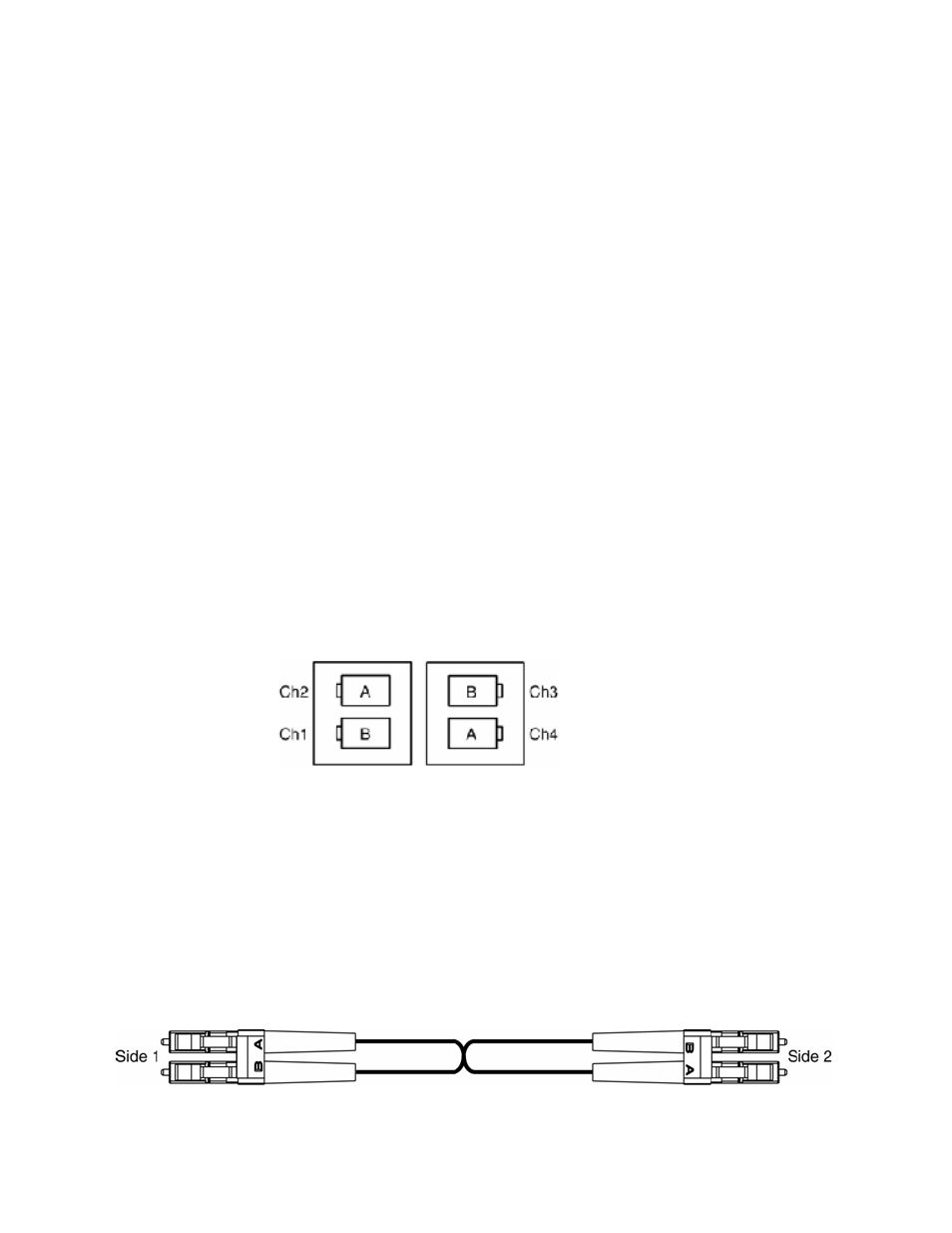
For the fiber output ports, the 8943CF-R rear module shall follow the
channel allocation convention shown in
. Optical channel 1 and
channel 3 are mapped to the B side of standard duplex fiber connector and
channel 2 and channel 4 are mapped to the A side of a standard duplex fiber
connector.
Figure 18. 8943CF to 8943CF Fiber Transmit Channels
8943CF to 8943FC Connections
When connecting an 8943CF module directly to an 8943FC (point-to-point),
a non-crossing duplex fiber cable is required shown in
. Refer to
for cable length attenuation notes.
Non-crossing is in reference to the logical A/B nomenclature associated
with the duplex connector illustrated below. Side 1A connects to side 2A
and side 1B connects to side 2B. Refer to
.
Figure 19. Non-Crossing Duplex Fiber Cable