Configuration procedure – H3C Technologies H3C WX5500E Series Access Controllers User Manual
Page 155
144
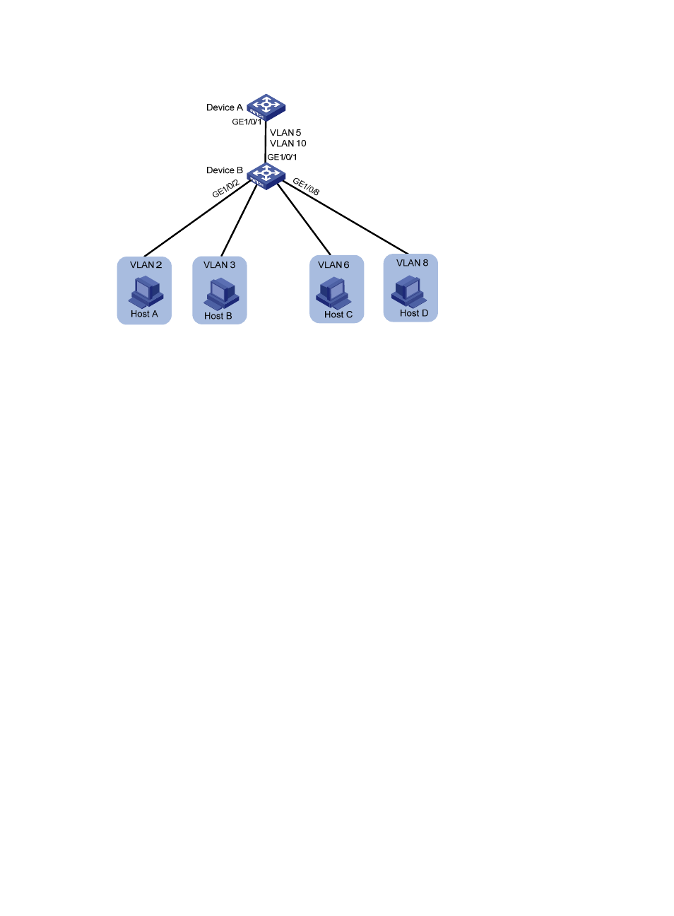
Figure 43 Network diagram
Configuration procedure
1.
Configure Device B:
# Configure VLAN 5 and VLAN 10 as isolate-user-VLANs.
[DeviceB] vlan 5
[DeviceB-vlan5] isolate-user-vlan enable
[DeviceB-vlan5] quit
[DeviceB] vlan 10
[DeviceB-vlan10] isolate-user-vlan enable
[DeviceB-vlan10] quit
# Create VLANs 2, 3, 6, and 8.
[DeviceB] vlan 2 to 3
[DeviceB] vlan 6
[DeviceB-vlan6] quit
[DeviceB] vlan 8
[DeviceB-vlan8] quit
# Associate secondary VLANs 2 and 3 with isolate-user-VLAN 5.
[DeviceB] isolate-user-vlan 5 secondary 2 to 3
# Associate secondary VLANs 6 and 8 with isolate-user-VLAN 10.
[DeviceB] isolate-user-vlan 10 secondary 6 8
# Configure the uplink port GigabitEthernet 1/0/1 to operate in promiscuous mode in VLANs 5
and 10.
[DeviceB] interface gigabitethernet 1/0/1
[DeviceB-GigabitEthernet1/0/1] port isolate-user-vlan 5 10 trunk promiscuous
[DeviceB-GigabitEthernet1/0/1] quit
# Assign the downlink port GigabitEthernet 1/0/2 to VLAN 2, and configure the port to operate
in host mode in VLAN 2. Assign the downlink port GigabitEthernet 1/0/3 to VLAN 3, and
configure the port to operate in host mode in VLAN 3.
[DeviceB] interface gigabitethernet 1/0/2
G
E
1
/0
/3
G
E
1
/0
/6