Layer 3 dynamic aggregation configuration example, Network requirements – H3C Technologies H3C S10500 Series Switches User Manual
Page 66
55
# Configure the global link-aggregation load-sharing criteria as the source and destination IP addresses
of packets.
[DeviceA] link-aggregation load-sharing mode source-ip destination-ip
2.
Configure Device B.
Configure Device B using the same instructions that you used to configure Device A.
3.
Verify the configurations.
# Display summary information about all aggregation groups on Device A.
[DeviceA] display link-aggregation summary
Aggregation Interface Type:
BAGG -- Bridge-Aggregation, RAGG -- Route-Aggregation
Aggregation Mode: S -- Static, D -- Dynamic
Loadsharing Type: Shar -- Loadsharing, NonS -- Non-Loadsharing
Actor System ID: 0x8000, 000f-e2ff-0001
AGG AGG Partner ID Select Unselect Share
Interface Mode Ports Ports Type
-------------------------------------------------------------------------------
RAGG1 S none 3 0 Shar
The output shows that link aggregation group 1 is a load-sharing-capable Layer 3 static aggregation
group that contains three Selected ports.
# Display the global link-aggregation load-sharing criteria on Device A.
[DeviceA] display link-aggregation load-sharing mode
Link-Aggregation Load-Sharing Mode:
destination-ip address, source-ip address
The output shows that the global link-aggregation load-sharing criteria are the source and destination IP
addresses of packets.
Layer 3 dynamic aggregation configuration example
Network requirements
As shown in
:
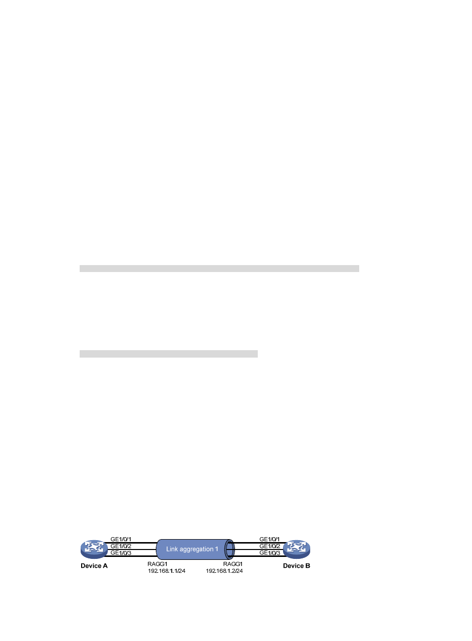
•
Device A and Device B are connected by their Layer 3 Ethernet interfaces GigabitEthernet 1/0/1
through GigabitEthernet 1/0/3.
•
Configure a Layer 3 dynamic aggregation group on Device A and Device B respectively and
configure IP addresses and subnet masks for the corresponding Layer 3 aggregate interfaces.
•
Enable traffic to be load-shared across aggregation group member ports based on source and
destination IP addresses.
Figure 15 Network diagram for Layer 3 dynamic aggregation