Vlan interface configuration example, Network requirements, Configuration procedure – H3C Technologies H3C S10500 Series Switches User Manual
Page 128
117
VLAN interface configuration example
Network requirements
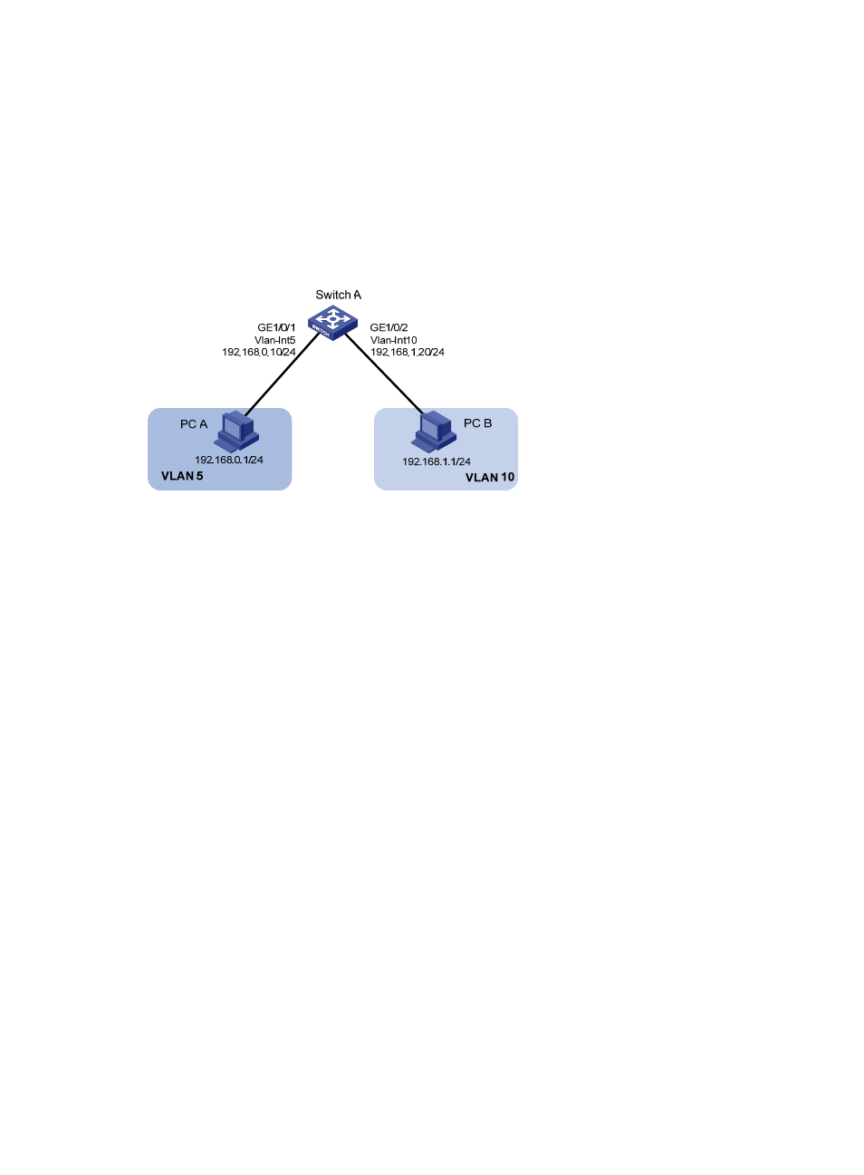
As shown in
, PC A is assigned to VLAN 5. PC B is assigned to VLAN 10. The PCs belong to
different IP subnets and cannot communicate with each other.
Configure VLAN interfaces on Switch A and configure the PCs to enable Layer 3 communication
between the PCs.
Figure 38 Network diagram for VLAN interface configuration
Configuration procedure
1.
Configure Switch A.
# Create VLAN 5 and assign GigabitEthernet 1/0/1 to it.
[SwitchA] vlan 5
[SwitchA-vlan5] port GigabitEthernet 1/0/1
# Create VLAN 10 and assign GigabitEthernet 1/0/2 to it.
[SwitchA-vlan5] quit
[SwitchA] vlan 10
[SwitchA-vlan10] port GigabitEthernet 1/0/2
[SwitchA-vlan10] quit
# Create VLAN-interface 5 and configure its IP address as 192.168.0.10/24.
[SwitchA] interface vlan-interface 5
[SwitchA-Vlan-interface5] ip address 192.168.0.10 24
[SwitchA-Vlan-interface5] quit
# Create VLAN-interface 10 and configure its IP address as 192.168.1.20/24.
[SwitchA] interface vlan-interface 10
[SwitchA-Vlan-interface10] ip address 192.168.1.20 24
[SwitchA-Vlan-interface10] return
2.
Configure PC A.
# Configure the default gateway of the PC as 192.168.0.10.
3.
Configure PC B.
# Configure the default gateway of the PC as 192.168.1.20.