Configuration procedure, N in, Figure 29 – H3C Technologies H3C S10500 Series Switches User Manual
Page 114
103
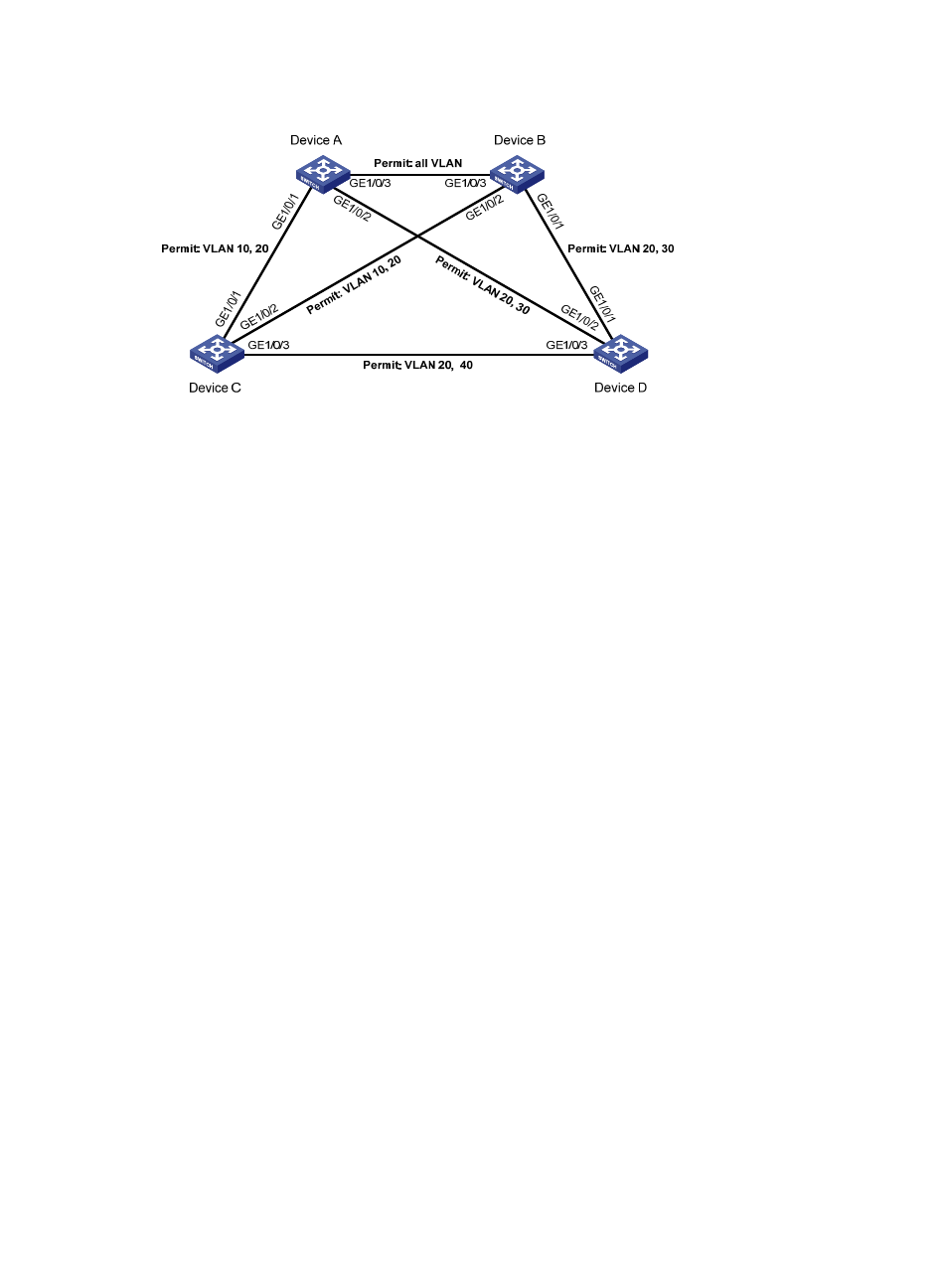
Figure 29 Network diagram for PVST configuration
Configuration procedure
1.
VLAN and VLAN member port configuration
Create VLAN 10, VLAN 20, and VLAN 30 on Device A and Device B respectively, VLAN 10, VLAN 20,
and VLAN 40 on Device C, and VLAN 20, VLAN 30, and VLAN 40 on Device D. Configure the ports
on these devices as trunk ports and assign them to related VLANs. The detailed configuration procedure
is omitted.
2.
Configuration on Device A
# Set the spanning tree mode to PVST.
[DeviceA] stp mode pvst
# Specify the device as the root bridge of VLAN 10 and VLAN 20.
[DeviceA] stp vlan 10 20 root primary
# Enable the spanning tree feature globally and for VLANs 10, 20, and 30.
[DeviceA] stp enable
[DeviceA] stp vlan 10 20 30 enable
3.
Configuration on Device B
# Set the spanning tree mode to PVST.
[DeviceB] stp mode pvst
# Specify the device as the root bridge of VLAN 30.
[DeviceB] stp vlan 30 root primary
# Enable the spanning tree feature globally and for VLANs 10, 20, and 30.
[DeviceB] stp enable
[DeviceB] stp vlan 10 20 30 enable
4.
Configuration on Device C.
# Set the spanning tree mode to PVST.
[DeviceC] stp mode pvst
# Specify the current device as the root bridge of VLAN 40.