Spanning tree configuration examples, Mstp configuration example, Network requirements – H3C Technologies H3C S10500 Series Switches User Manual
Page 110: Configuration procedure
99
Spanning tree configuration examples
MSTP configuration example
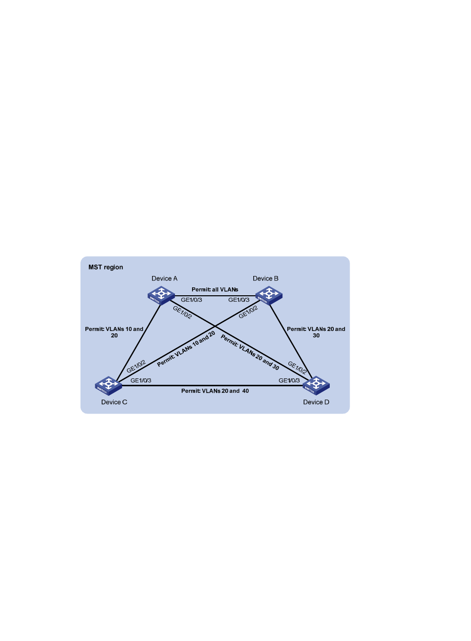
Network requirements
As shown in
•
All devices on the network are in the same MST region. Device A and Device B work at the
distribution layer. Device C and Device D work at the access layer.
•
Configure MSTP so that packets of different VLANs are forwarded along different spanning trees:
Packets of VLAN 10 are forwarded along MSTI 1, those of VLAN 30 are forwarded along MSTI 3,
those of VLAN 40 are forwarded along MSTI 4, and those of VLAN 20 are forwarded along MSTI
0.
•
VLAN 10 and VLAN 30 are terminated on the distribution layer devices, and VLAN 40 is
terminated on the access layer devices. The root bridges of MSTI 1 and MSTI 3 are Device A and
Device B respectively, and the root bridge of MSTI 4 is Device C.
Figure 27 Network diagram for MSTP configuration
G
E
1
/0
/1
G
E
1
/0
/1
G
E
1
/0
/1
G
E
1
/0
/1
Configuration procedure
1.
Configure VLANs and VLAN member ports (details not shown).
Create VLAN 10, VLAN 20, and VLAN 30 on Device A and Device B respectively, VLAN 10, VLAN 20,
and VLAN 40 on Device C, and VLAN 20, VLAN 30, and VLAN 40 on Device D. Configure the ports
on these devices as trunk ports and assign them to related VLANs.
2.
Configure Device A.
# Enter MST region view; configure the MST region name as example; map VLAN 10, VLAN 30, and
VLAN 40 to MSTI 1, MSTI 3, and MSTI 4, respectively; configure the revision level of the MST region as
0.
[DeviceA] stp region-configuration
[DeviceA-mst-region] region-name example
[DeviceA-mst-region] instance 1 vlan 10