Configuring loop detection, Overview, Loop detection mechanism – H3C Technologies H3C S12500-X Series Switches User Manual
Page 113: Stp configuration task list, Rstp configuration task list

102
Configuring loop detection
Overview
Incorrect network connections or configurations can create Layer 2 loops, which results in repeated
transmission of broadcasts, multicasts, or unknown unicasts, waste network resources, and sometimes
even paralyze networks. The loop detection mechanism immediately generates a log when a loop occurs
so that you are promptly notified to adjust network connections and configurations. You can even
configure loop detection to shut down the looped port. Logs are maintained in the information center. For
more information, see Network Management and Monitoring Configuration Guide.
Loop detection mechanism
The device detects loops by sending detection frames and then checking whether these frames return to
any port on the device. If they do, the device considers that the port is on a looped link.
Loop detection usually works within a VLAN. If a detection frame is returned with a VLAN tag different
from the one it is sent out with, an inter-VLAN loop has occurred. To remove the loop, examine the QinQ
configuration for incorrect settings. For more information about QinQ, see "Configuring QinQ".
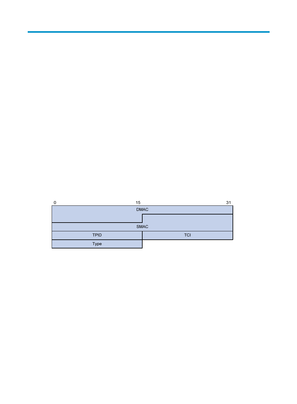
Figure 27 Ethernet frame header for loop detection
The Ethernet frame header for loop detection contains the following fields:
•
DMAC—Destination MAC address of the frame, which is the multicast MAC address
010F-E200-0007. When a loop detection-enabled device receives a frame with this destination
MAC address, it sends the frame to the CPU and floods the frame in the VLAN from which the frame
was originally received.
•
SMAC—Source MAC address of the frame, which is the bridge MAC address of the sending
device.
•
TPID—Type of the VLAN tag, with the value of 0x8100.
•
TCI—Information of the VLAN tag, including the priority and VLAN ID.
•
Type—Protocol type, with the value of 0x8918.
