6 test, User setting – ARAG GCS 3200 User Manual
Page 31
31
13.6
Test
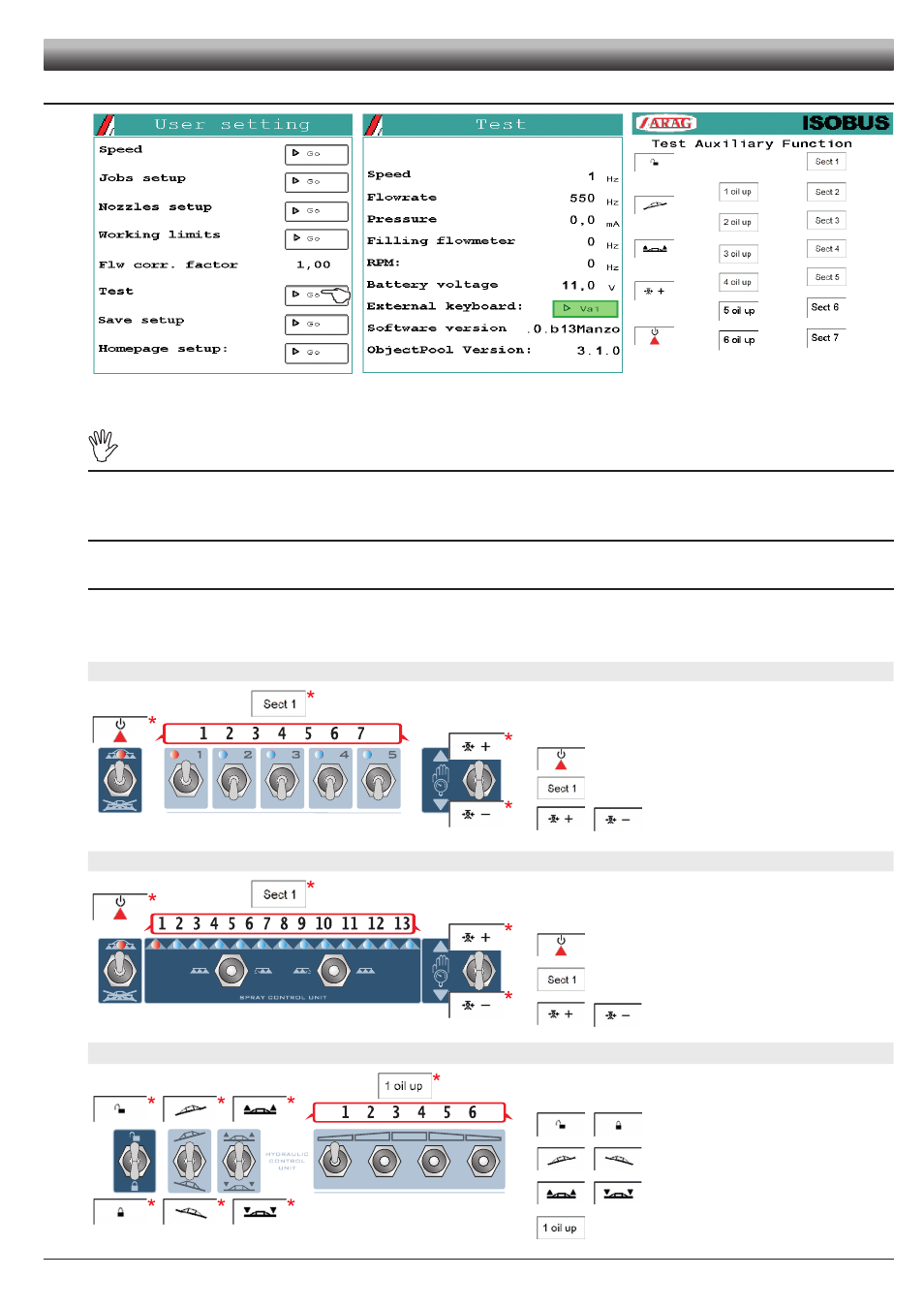
Fig. 66
Fig. 67
Fig. 68
Allows checking the correct operation of the ISOBUS Job Computer.
TESTS ARE READING-ONLY DATA.
Signal test
The device detects frequency and current sent by each sensor on the system (Fig. 67).
Displays the version of the installed software and object pool (Fig. 67).
Battery voltage
The ISOBUS system displays the supply voltage.
External push-button panel
Checks the operation of the Auxiliary input commands.
Switch on the switches: if the operation is correct, the display shows the relevant command. (Fig. 68).
H2O panel, RCU VERSION
Fig. 69
*
Displayed symbols (Fig. 68)
H2O switches:
Main control ON
1
/
2
/
3
/
4
/
5
/
6
/
7
Section valve 1 ON
/
Proportional regulation
(
+
increase /
-
decrease)
H2O panel, SEQUENTIAL RCU VERSION
Fig. 70
*
Displayed symbols (Fig. 68)
H2O switches:
Main control ON
1
/
2
/
3
/
4
/
5
/
6
/
7
/
8
/
9
/
10
/
11
/
12
/
13
Section valve 1 ON
/
Proportional regulation
(
+
increase /
-
decrease)
Hydraulic function panel
Fig. 71
*
Displayed symbols (Fig. 68)
Hydraulic function switches:
(if hydraulic functions are available, ONLY)
/
Release /
Lock
/
Inclination:
Left /
Right
/
Boom height:
Lift /
Lower
Hydraulic functions:
1
2
3
4
5
6
Function enabling 1
USER SETTING