9 error display and output – AEC WD 350 through WD3000 Dehumidifying Dryers User Manual
Page 61
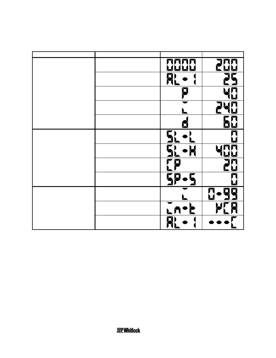
Figure 17
Level 2 Controller Factory Preset Parameters
Parameter setting level
Parameter description
PV LED display
SV LED display
Process temperature display
at power-up (º)
Alarm 1 value (high; º)
Proportional band (º)
Reset time (sec)
0
Rate time (sec)
Lower limit of control range (º)
Upper limit of control range (º)
Heating control period (º)
1
Shift set value (º)
Control output variable (%)
Temperature sensor type
2
Alarm #1 mode
These parameters display only if the #6 position of the FUNCTION selector switch is set in the ON
position.
Level 2 variables are read-only for monitoring use only. Do not set these variables!
7-9 Error Display and Output
The controller that comes with your dryer incorporates a self-diagnostic function. The table on
the following page lists process values and outputs the controller displays when errors occur.
Page 60
WDMR and WDFR Series Dehumidifying Dryers