AEC WD 350 through WD3000 Dehumidifying Dryers User Manual
Page 57
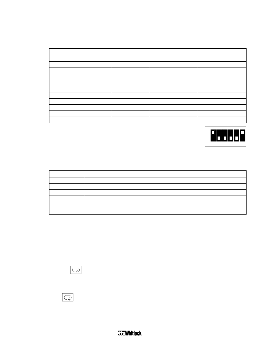
Note the settings for thermocouples on the following table:
Sensor Switch Temperature
range
type position
°F
°C
Thermocouple Type K
0
—
0 to 200
Thermocouple Type K
1
—
0 to 300
Thermocouple Type K
2
0 to 400
0 to 400
Thermocouple Type K
3
0 to 500
0 to 500
Thermocouple Type K
4
0 to 600
0 to 600
Thermocouple Type K
5
0 to 999
0 to 999
Thermocouple Type J
6
0 to 999
0 to 200
Thermocouple Type J
7
—
0 to 300
Thermocouple Type J
8
0 to 400
0 to 400
Thermocouple Type J
9
0 to 500
0 to 500
1
2
3
4
5
6
ON
OFF
FUNCTION
6. The function selector DIP switch marked
FUNCTION
lets you select
controller modes. It is located on the back of the display.
Put this switch in the setup configuration as shown in the following table while entering
initial control parameters.
Setup Configuration
1 ON
PID Controller mode
2 OFF
20-second proportional period
3 OFF
Reverse control output (heating)
4 OFF
Input shift disabled
5 OFF
JIS sensor standard
6 ON
ºF scaling indication
7. Slide the control chassis back into the control housing. Set the remaining parameters with
the keypad.
8. Prepare your dryer for startup with a real or simulated load. Restore electrical power.
9. Turn on control power.
The
PV
LED displays
000
(zeros), then displays the current process air temperature.
10. Press the
Mode key once to toggle between the actual process display and the
SV
LED set value display.
The
SV
LED displays the current process air temperature set point.
11. Press
again.
The
AL
alarm indicator lights.
Page 56
WDMR and WDFR Series Dehumidifying Dryers