Cabling, Auxiliary ports, Cabling -2 – Verilink AS56/56Plus (896-502588-001) Product Manual User Manual
Page 80: Auxiliary ports -2
Auxiliary Ports
6-2
AS56 and AS56
Plus
User Manual
Cabling
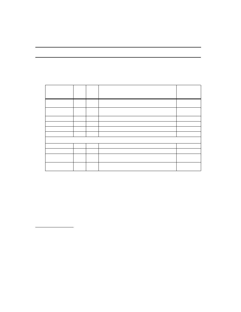
The table below provides a summary of the Verilink cables available for
the Centum series.
For additional cable and pinout detail, see the following sections of this
manual:
■
Appendix A, Standard Cabling for User Ports
■
Appendix B, Special Serial Port Cabling.
Auxiliary ports
Both auxiliary ports consist of 9-pin D-type female connectors. Because
the ports are permanently DCE, there are two configurations for the
required cabling, depending on whether the connections are “direct” or
via modems.
Verilink Cable
Number
Length
Shipped
with
Product
Description
Type of Cable
CBE 010-56001
15 ft.
Yes
8-pin to 8-pin modular Male-to-Male for network
connection
Networ
CBE 020-09025
4 ft.
Yes
DE-9 male to DB-25 male for direct connection to
mode
Management
458-501983-015
15 ft.
No
V.35 Male to Male, DCE to DTE
Application
458-501792-015
15 ft.
No
25D-type with RS-530 specification. Male-to-Male
Application
458-501776-015
15 ft.
No
V.35 Male-to-Male for external timin
a
Application
458-501791-015
15 ft.
No
RS-530 Male-to-Male for external timing
a
Application
Adapter Cables
b
(below)
458-502361-015
15 ft.
No
25D-type (RS-530) Male to 37-pin (RS-449) Female
Application
458-502362-015
15 ft.
No
25D-type (RS-530) Male to 37-pin (RS-449) Male
Application
458-502363-015
15 ft.
No
25D-type (RS-530) Male to 37-pin (RS-449) Female
for external timing
a
Application
458-502364-015
15 ft.
No
25D-type (RS-530) Male to 37-pin (RS-449) Male for
external timing
a
Application
a. External Timing is the same as DSU-X, for a cross-over cable.
b. Adapter cables are used to convert between a 25-pin connector on the rear of the box to a 37-pin con
nector on the customer apparatus.