Front and entrance end view – Rena T-650 User Manual
Page 8
GETTING ACQUAINTED
4
5
6
7
14
11
13
8
1
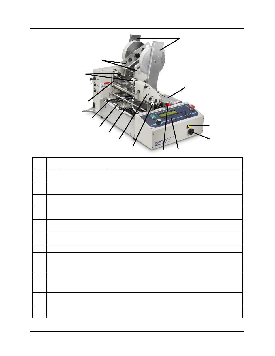
Front and Entrance End View
10
9
12
3
2
1
Control Panel – The machine is controlled and programmed from this panel.
See “
2
Head 1 Fine Adjustment Knob – This knob is used to make fine adjustments to the
position of the tab/stamp, being applied by Head 1.
3
Head 2 Fine Adjustment Knob – This knob is used to make fine adjustments to the
position of the tab/stamp, being applied by Head 2.
4
Head 1 – This head can be used to apply tabs to the side or leading edge of the media or
it can be used to apply stamps.
5
Right Media Guide Assembly – This device must be adjusted to accommodate the
width of the media. Delivers the media to the tabbing area.
6
Center Support Plate – Used to support media 6.5” wide or larger. This plate also
contains the slot used in the process of front tabbing (tabbing at leading edge).
7
Left Media Guide Assembly - Delivers the media to the tabbing area. Its position is not
adjustable.
8
Head 2 – This head is used to apply tabs to the side of the media.
9
Take-up Reels – After the tab is applied; the tab backing (web) is wound up here.
The backing waste must be cleared from these reels after applying about 5,000 tabs.
10
Tab Reel Side Guides - Secures the Tabs/Stamps onto the Tab Reel Assembly.
11
Tab Reel Assembly (H1 & H2) – Supports and controls the tab/stamp roll for Head.
12
Exit Roller Assembly –This assembly presses the tab/stamp to the media and provides
sufficient transport pressure, so the media properly exits the tabber.
13
Media Guide Width Fine Adjustment– This knob is used to fine-tune the position of
the “Right Media Guide Assembly” to accommodate the width of the media.
14
Media Thickness Adjustment Knob – This knob is used to raise or lower the Heads
and Exit Roller Assembly when adjusting the tabber to the thickness of the media.
T-650 Operations REV. 8/25/2010
8