Daq/112b and daq/216b pc-cards, Configuration, Daq pc-cards – Measurement Computing Daq PC-Card User Manual
Page 53: Daq/112b, Daq/216b, Daq pc-card
DaqBook/DaqBoard/Daq PC-Card User’s Manual
05-11-00
Daq* Hardware 3-23
Daq/112B and Daq/216B PC-Cards
The Daq PC-Card for notebook PCs complies with PC Card Standard Specification 2.1, PCMCIA Type II
(5mm) compatible. The Daq/112B and Daq/216B provide 12- or 16- bit, 100 kHz data acquisition via
8 differential or 16 single-ended analog inputs. A variety of signal-conditioning, expansion, and software
options are available. The Daq PC-Card connects to DBK cards and modules that support the DB37 (P1)
connector.
Input power for the Daq PC-Card comes from the host computer. No output power is available. Thus,
power for DBKs must be provided by a CDK10. A CDK10 expansion chassis also has two card slots to
hold DBKs. For expansion, the DBK41 (10-Slot Chassis) or DBK60 (3-Slot Chassis with Termination
Panels) with the DBK32A or DBK33 can be used for multiple DBK Cards.
The on-board 512-location scan sequencer allows you to select any channel and gain to scan different types
of transducers, from thermocouples to strain gauges, within the same scan group without a software slow
down. The sequencer scans at a 10 µs/channel rate and can be programmed to repeat a sequence at
intervals from 10 µs to 10 hr. Optional simultaneous sample and hold cards can sample up to 256 channels
at the same instant. Scanning and timing specifications are met even with a full complement of expansion
modules (maximum of 256 input channels).
The Daq PC-Card includes DOS-based client software that is compatible with PCMCIA Card Services
Specification 2.1. This software allows easy insertion and removal into any Type II socket with automatic
configuration on insertion for DOS and Windows 3.x. (CardSoft™ Card and Socket Services are available
on most notebook PCs or from various sources. If using Windows 95/98/ME, the installation disk has a
configuration file and does not require additional PCMCIA software.)
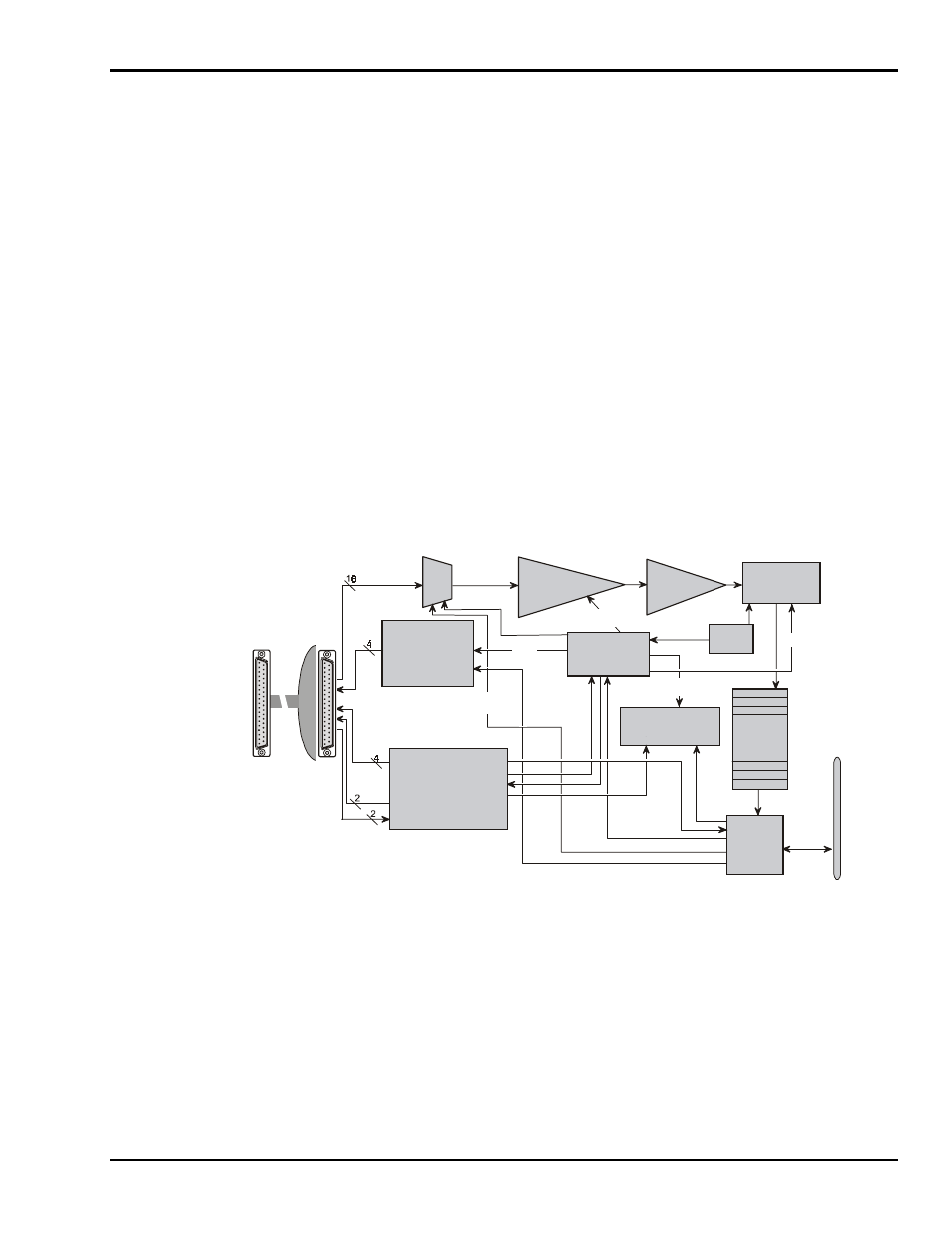
The figure shows the Daq PC-Card block diagram.
8 D E /1 6 S E
analog in put
m ultiplexer
S am ple &
hold am plifier
100 kH z
clock
12 or 16-bit,
100 kHz
analog to digital
converter
512-step
random access
channel/gain
sequencer
P C M CIA
Interface
8-bit
data &
address
bus
P rogram m able
gain am plifier
×1,2,4,8
4 general purpose
digital inputs
or
E xternal clock gate
1 TTL trigger input
2 gain select outputs for
expansion boards
4 digital outputs
for high-speed
channel expansion
or
4 general purpose
digital outputs
2K w ord
FIFO
data
buffer
A N A LO G I/O
v ia op tio nal
c able
C A -134
D B 37
(D A S -1 6
c om patible)
P1
S ign al
I/O
S equencer
reset
E xternal
M U X
C ontrol
M UX
G ain select
per channel
P C M C IA
P ort
o f P C
P rogram m able
sequencer tim ebase,
10 s to 167s
u
S E /D E
s ele ction
B ipolar
Daq PC-Card Block Diagram
Configuration
The Daq PC-Card does not require hardware configuration. No jumpers, no switches—all configuration
occurs in software. You will have to install the software before performing the configuration.
Note: You may need to set jumpers in your DBKs or other system components.
I/O Configuration
Data is transferred to the host computer via the PCMCIA interface. This interface provides access to the
PC’s data bus, allowing real-time data collection and storage to disk at 100 K readings/s. The built-in
512-word FIFO prevents data loss. Two data transfer modes are supported:
•
The programmed I/O mode allows the computer to acquire individual data samples or large blocks of
data under application control.