Measurement Computing Daq PC-Card User Manual
Page 35
Daq* Hardware
DaqBook/100, /112, /120, /200, /216
DaqBook/DaqBoard/Daq PC-Card User’s Manual
10-18-00
3-5
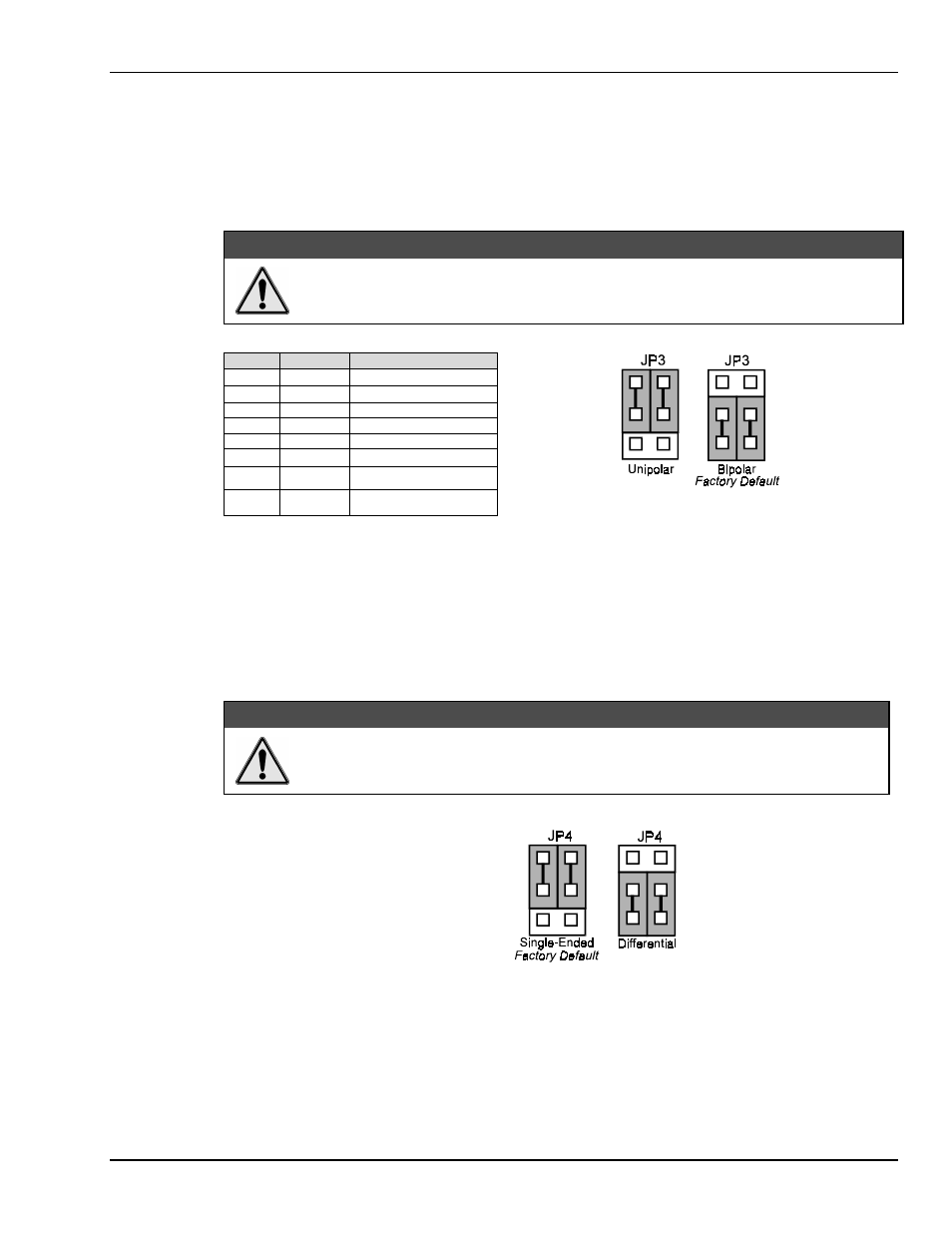
Bipolar or Unipolar A/D Operation (JP3)*
*Hardware Setting For DaqBook/100, /112, and /120 Only
The A/D converter in the DaqBook can be operated in two modes, bipolar or unipolar. In the bipolar mode
(default setting), input voltages up to ±5 VDC can be applied (on the ×1 gain range). In the unipolar mode,
positive voltages up to 10 VDC may be applied (×1 gain range). Refer to the table below for gain, range,
and mode relations.
&$87,21
JP3 is a double-wide jumper that must be positioned vertically. Misplacing this jumper
in a horizontal position will damage the unit.
Gain
Mode
Volts Range
×1
BI
±5
×2
BI
±2.5
×4
BI
±1.25
×8
BI
±0.625
×1
UNI
0 to +10
×2
UNI
0 to +5
×4
UNI
0 to +2.5
×8
UNI
0 to +1.25
JP3 Unipolar/Bipolar Operation Settings
Note: For the DaqBook/100, /112, and /120, set the jumpers to the desired position as shown in figure.
Note: For the DaqBook/200, /216, and /260 the Unipolar/Bipolar option is selected via software by the
daq200SetMode and daq200SetScan commands.
Single-ended or Differential Analog Input Channels (JP4)*
*Hardware Setting For DaqBook/100, /112, and /120 Only
&$87,21
JP4 must be positioned vertically. Positioning JP4 horizontally will damage the unit.
JP4 Single-Ended/Differential Settings
JP4 is a 3×2 header used to configure the 16 analog input lines as 16 single-ended channels or as 8 pairs of
differential channels. In general, if the DaqBook is going to be used in the stand-alone mode (no analog
expansion cards), either mode can be used. If analog expansion cards (each DBK capable of
sixteen single-ended or differential inputs) are used, the single-ended mode must be used. The default
setting is thus single-ended. Place the jumpers in the desired position (see figure).
Note: For the DaqBook/200, /216, and /260, the Unipolar/Bipolar option is selected via software by the
daq200SetMode and daq200SetScan commands.