Connections – Measurement Computing Daq PC-Card User Manual
Page 51
Daq* Hardware
DaqBoards [ISA-types Only]
DaqBook / DaqBoard [ISA-types] / Daq PC-Card User’s Manual
10-18-00
Daq* Hardware 3-21
Connections
Installation
Refer to the DaqBoard [ISA types] section of chapter 1,
, for the installation procedure.
I/O Connectors
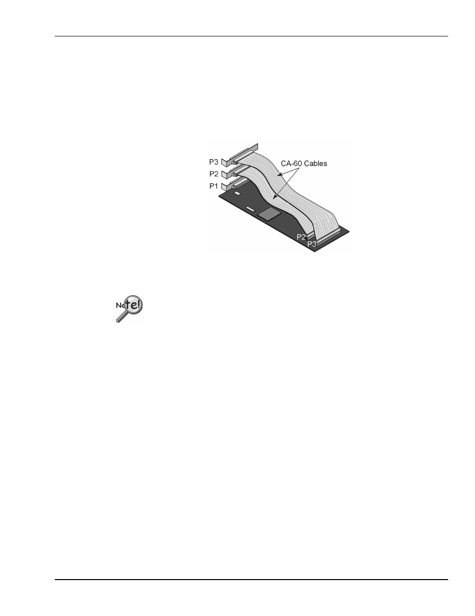
The DaqBoard accepts all analog and digital I/O signals via one standard I/O connector (P1) and two on-
board 40-pin headers (P2 and P3 on the DaqBoard/100A/200A). The CA-60 cable can be used as an
interface between the onboard P2 and P3 and a DB37 connector on the outside of the computer’s enclosure.
•
P1 Analog I/O. Provides 16 analog input channels, 2 analog output channels, a 16-bit counter/timer,
4 TTL inputs and outputs, and various signals for driving expansion cards.
•
P2 Digital I/O. Provides (3) 8-bit TTL programmable I/O ports and external interrupt input.
P2 expansion cables must be kept relatively short to ensure reliable operation. Do not
exceed 14 inches per attached DBK card.
•
P3 Frequency I/O. Provides (5) 16-bit counters and 16 high-speed digital inputs and external
interrupt input.
To gain access to the DaqBoard port connectors, signals can be connected via CA-131-x cable through a
D-shell 37-pin female connector or a DBK11 screw-terminal option card with component sockets.