2) make board connections, Calibration, Dma and interrupt – Measurement Computing Daq PC-Card User Manual
Page 16: Base address
1-8 DaqBoard [ISA Type] Quick Start Guide
01-11-00
457-0942, rev 1.2
JP7 –
Calibration
Leave JP7 in default position. Only use JP7 during calibration. See user’s manual.
JP8 –
DMA and Interrupt
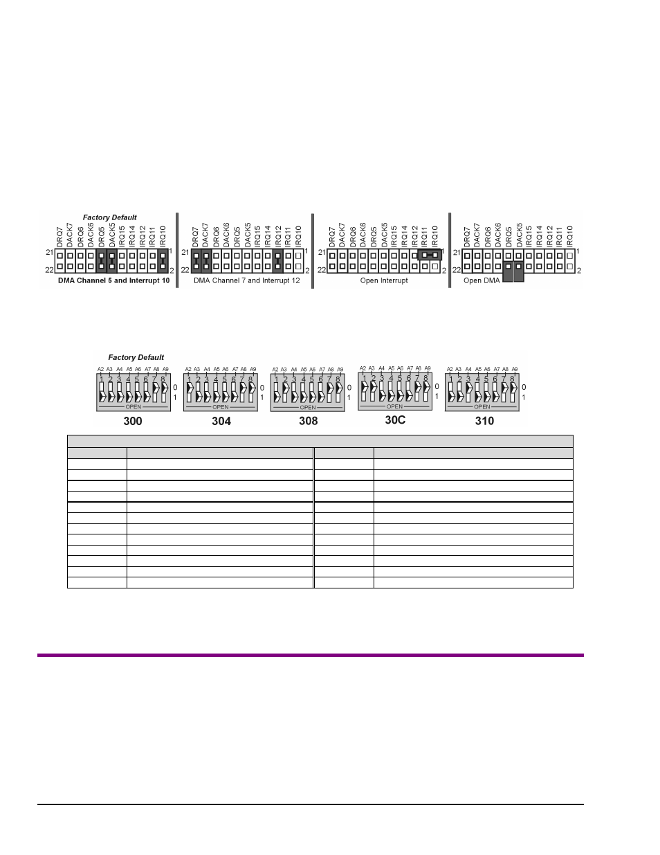
Interrupt Selection. DaqBoard may be set to interrupt the PC when certain hardware conditions occur. The interrupt may
be set to IRQ level 10, 11, 12, 14 or 15. DaqBoard’s IRQ level cannot be shared with another device. To disable interrupt
assistance and background transfers you can configure JP8 to “Open Interrupt” (see following figure).
DMA Selection. Direct Memory Access (DMA) configuration provides for:
(a)
high-speed data transfer from the ADC FIFO, or
(b)
high-speed data transfer to the DAC FIFO.
Only DMA channels 5-7 (of an ISA AT machine’s seven channels) are available to DaqBoard.
Set DRQ and DACK jumpers to the desired DMA channels. Note that DaqBoard does not share DMA channels.
Set the DMA jumpers to OPEN when other devices will be using DMA channels 5, 6 and 7.
SW1
- Base Address
SW1’s factory default is 300 Hex. If 300 Hex presents an address conflict, set a new SW1 address within the range of
1FF to 3FF (256 to 1023 Decimal). Note that the address must be on a 4-byte boundary.
(2) Make Board Connections
Before connecting your DaqBoard, you should review the following connector descriptions.
P1 Analog I/O. Provides 16 analog input channels, 2 analog output channels, a 16-bit counter/timer, 4 TTL inputs and
outputs, and various signals for driving expansion cards.
P2 Digital I/O. Provides three 8-bit TTL programmable I/O ports and external interrupt input. To ensure reliable
operation, for P2 expansion cables do not exceed 14 inches per attached DBK card.
P3 Frequency I/O. Provides five 16-bit counters and 16 high-speed digital inputs and external interrupt input.
Industry Standard I/O Addresses
Hex Range
Device
Hex Range
Device
000-1FF
Internal system
368-36B
PC network (high address)
200-207
Game I/O
36C-36F
Reserved
20C-20D
Reserved
378-37F
Parallel printer port 1
21F
Reserved
380-38F
SDLC, bisynchronous 2
278-27F
Parallel printer port 2
390-393
Reserved
2B0-2DF
Alternate enhanced graphics adapter
3A0-3AF
Bisynchronous 1
2E1
GPIB (Adapter 0)
3B0-3BF
Monochrome display and printer adapter
2E2 & 2E3
Data acquisition (Adapter 0)
3C0-3CF
Enhanced graphics adapter
2F8-2FF
Serial port 2
3D0-3DF
Color/Graphics monitor adapter
300-31F
Prototype card
3F0-3F7
Diskette Controller
360-363
PC network (low address)
3F8-3FF
Serial port 1
364-367
Reserved
Notes:
(1) SW1’s address must be unique, i.e., not used by another device.
(2) I/O addresses, hex 000 to 0FF, are reserved for system board I/O.
(3) Hex 100 to 3FF are available on the I/O channel.
(4) Although the above table represents industry standards, some systems may vary.