Jumpers – Measurement Computing Daq PC-Card User Manual
Page 33
Daq* Hardware
DaqBook/100, /112, /120, /200, /216
DaqBook/DaqBoard/Daq PC-Card User’s Manual
10-18-00
3-3
DaqBook Controls and Connectors
Switch
POWER
Depressing the “1” side of this rocker-arm switch turns the power on.
Connectors
POWER INPUT
This DIN5 input connector accepts +7 to 20 VDC for the /100, /112, /120;
+10 to 24 VDC for the /216; +9 to 18 VDC for the /200, /260.
TO PARALLEL PRINTER
This port allows the computer to use any standard parallel printer in a
pass-through mode (DB25).
FROM PC PARALLEL PORT
This port connects to the computer’s standard or enhanced parallel port
(DB25).
P1 - ANALOG I/O
Provides sixteen analog input channels, two analog output channels,
two 16-bit counter/timers, four TTL inputs and outputs, and various signals
for driving expansion cards (DB37).
P2 - DIGITAL I/O
Provides three 8-bit TTL programmable I/O ports and external interrupt input
(DB37).
P3 - FREQUENCY I/O
Provides five 16-bit counters and sixteen high-speed digital inputs and
external interrupt input (DB37).
Indicators
POWER
This LED lights when power is applied to the DaqBook and the power switch
is in the “1” (ON) position.
P1-P2-P3 ACTIVE
This LED lights when the DaqBook is in an active state. This LED is off
when the DaqBook is disabled or in the printer-pass-through mode. P1,
P2, and P3 are software accessible from the computer.
BUFFER OVERRUN
This LED lights for a buffer overrun error. This occurs when A/D signals are
converted faster than the PC collects the data. Depending on the
application, this indication may not be an error.
A/D ACTIVE
This LED lights during an A/D scan sequence. If the sequence has a low
number of steps and occurs infrequently, this indicator will only flash
briefly.
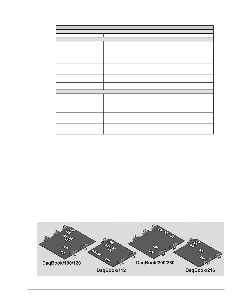
Jumpers
Proper installation requires that several jumpers and switches be set correctly for your application. These
jumpers and switches are located inside the DaqBook enclosure and possibly on your DBKs. Jumpers for
the various DaqBook models are configured similarly except for the jumpers’ relative locations. Silk-
screening on the motherboard identifies jumpers and switches. Note: Even if using the default settings, you
should verify actual jumper positions.
The DaqBook configuration jumpers include:
•
JP1 - External Analog Expansion Power
•
JP2 - DAC Voltage Reference
•
JP3* - Unipolar/Bipolar
•
JP4* - Differential/Single Ended
•
JP5 - Time Base
•
JP6 - Watchdog Timer Enable
•
JP7 - Calibration (refer to
Chapter 12, Calibration
)
* The DaqBook/200, /216, and /260 do not have JP3 and JP4 jumpers—these settings are made via
software.
Location of DaqBook Jumpers