Front and rear panels, Daqbook block diagram – Measurement Computing Daq PC-Card User Manual
Page 32
DaqBook/100, /112, /120, /200, /216
Daq* Hardware
3-2
10-18-00
DaqBook/DaqBoard/Daq PC-Card User’s Manual
8 DE/16 SE
analog input
multiplexer
512-step, random access
channel/gain sequencer
Programmable
sequencer
timebase.
10 us to 12 hrs
24-bit general purpose
digital I/O lines
16 high-speed
digital inputs
5 counter/timer
channels
4K word
FIFO
data
buffer
Sequencer
reset
P2*
DIGITAL I/O
P1
ANALOG I/O
Signal
I/O
Computer
I/O
(DAS-16
compatible)
(PIO-12
compatible)
(CTM-05
compatible)
P3*
PULSE/FREQ.
HIGH-SPEED
DIGITAL I/O
PGA
per channel
Amplifier
x1, x2
x4, x8
100kHz
Clock
4 general purpose
digital inputs
-or-
1 auxiliary counter gate
1 TTL trigger input
2 gain select for expansion
Analog Trigger-
Comparator
12 or 16-bit,
100 kHz, A-to-D
Converter
Dual 12-bit DAC
-or-
4 digital outputs
for high-speed
channel expansion
4 general purpose
digital outputs
P5
pass-through
to printer
P4
to PC
parallel
port
or EPP*
VDC
Power In
DC-DC
converter
+5
+15
-15
Hold
Sample
&
Trigger
Select
*Models /100, /120, /200, and /260 only
**Models /112, /120, /200, and /216 only
(+7-20 VDC for /100, /112, and /120)
(+9-18 VDC for /200)
(+10-24 VDC for /216)
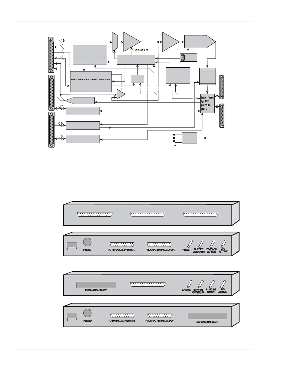
DaqBook Block Diagram
Front and Rear Panels
The following figures show the location of controls and connectors on the DaqBook exteriors. These
locations vary by model (DaqBook/100, /120, and /200 versus the DaqBook/112 and /216).
Fro n t P a ne l of D aq B o ok/11 2/2 1 6
R e ar P an el o f D a qB o o k/112 /21 6
P 1 - A N A LO G I/O
Fro n t P a ne l of D aq B o ok/1 00 /12 0 /20 0
P 1 - A N A LO G I/O
P 2 - D IGITA L I/O
P 3 - FR E QU E N C Y I/O
R e ar P an el o f D a qB o o k/1 0 0/1 20 /2 00