Measurement Computing Daq PC-Card User Manual
Page 44
DaqBook/260
Daq* Hardware
3-14
1-14-00
DaqBook/DaqBoard/Daq PC-Card User’s Manual
6 – Configure chassis for power sources
Avoid having more than one power source on the P1 bus. +5 V is controlled by the JP1 and JP2 on the P1
interconnect board. ±15 V is controlled by the JP1 on the DaqBook/200 acquisition processor board.
A.
JP2 on interconnect board – If +5 V will be supplied to DBK cards outside the chassis, install the JP2 jumper
on the P1 interconnect board (see figure).
B.
JP1 on interconnect board – If +5 V will be supplied to DBK cards inside the chassis, install the JP1 jumper
on the P1 interconnect board (see figure).
C.
JP1 on acquisition processor board – If using a DBK32A or DBK33 power card anywhere in the system,
remove the +15 V/-15 V jumpers from JP1 on the DaqBook/200 acquisition processor board. Refer to
Hardware Setup in the DBK32A or DBK33 section of this manual.
7 – Install power card if necessary
If you determined in step 5 that additional power is needed, add a DBK32A or DBK33 power card to the
chassis. (The CDK10 power card is housed in its own chassis.)
A.
Carefully align the power card’s DB37 connector with a DB37 connector on the interconnect board and
gently press them together.
B.
Mount the power card with two screws into the standoffs on the card drawer.
8 – Configure DaqBook/260
If a DaqBook/260 driver is not available in software, select DaqBook/200. Refer to other parts of this chapter,
as needed.
9 – Configure DBK cards
Configure unique channel addresses with the jumpers on the DBK cards. Some cards have other jumpers and/or
DIP switches. Refer to the particular DBK sections of this manual, as needed.
10 – Install DBK cards
You must use all analog DBK cards in the DaqBook/260. (A factory modification is available to use all digital
cards.)
A.
Carefully align the DBK card’s DB37 connector with a DB37 connector on the interconnect board and gently
press them together (see figure).
B.
Mount the DBK card with two screws into the standoffs on the card drawer.
C.
Continue installation of any remaining DBK cards.
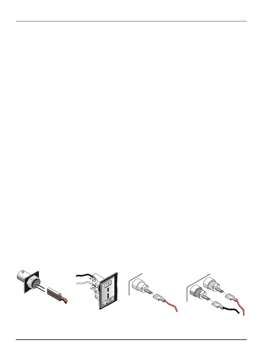
11 – Connect internal signals
Connect signal inputs from DBK cards to termination panels. DBK cards connect to the termination panels in
various ways (see figure and particular DBK sections in manual):
•
Single-ended connections use analog common.
•
Differential connections require the proper polarity, typically red-to-red for high (+) and black-to-black for
low (-).
•
For thermocouples, red is generally the low side, and the T/C connector and wire type must match the T/C
type used.
B NC C onne cto r
+
_
Term in ation P a nel
(
)
interna l s ide
R ed
H igh (+ )
B lac k
Lo w (-)
Te rm ina tio n P a ne l
(
)
e x terna l s id e
H igh (+ )
L ow (-)
R e d
T/C C onnec tor
Lo w (-) c onn ec ts to
an alog co m m on
(n ot sh ow n).
Term in ation P a nel
(
)
interna l s ide
S afety Jac k Con nector
(
)
S ing le-e nde d us e
R e d
H igh (+ )
B lac k
Lo w (-)
R ed
H igh (+ )
Term in ation P a nel
(
)
interna l s ide
S afety Jac k Con nectors
(
)
D ifferential us e