3) connect the interface cable – Measurement Computing Daq PC-Card User Manual
Page 22
1-14 Daq PC-Cards Quick Start Guide
01-11-00
457-0943, rev 1.2
Address Range that your system has already allocated to another device. Consult your user’s manual if this
is the case, or if you desire more control of your software configuration.
(3) Connect the Interface Cable
Digital I/O is supported and includes four general-purpose digital inputs and four general-purpose digital
outputs. The PC can access these TTL-level digital I/O lines when the Daq PC-Card is not transferring data
from the A/D converter. These I/O lines are not available if using P1 expansion cards or DBKs.
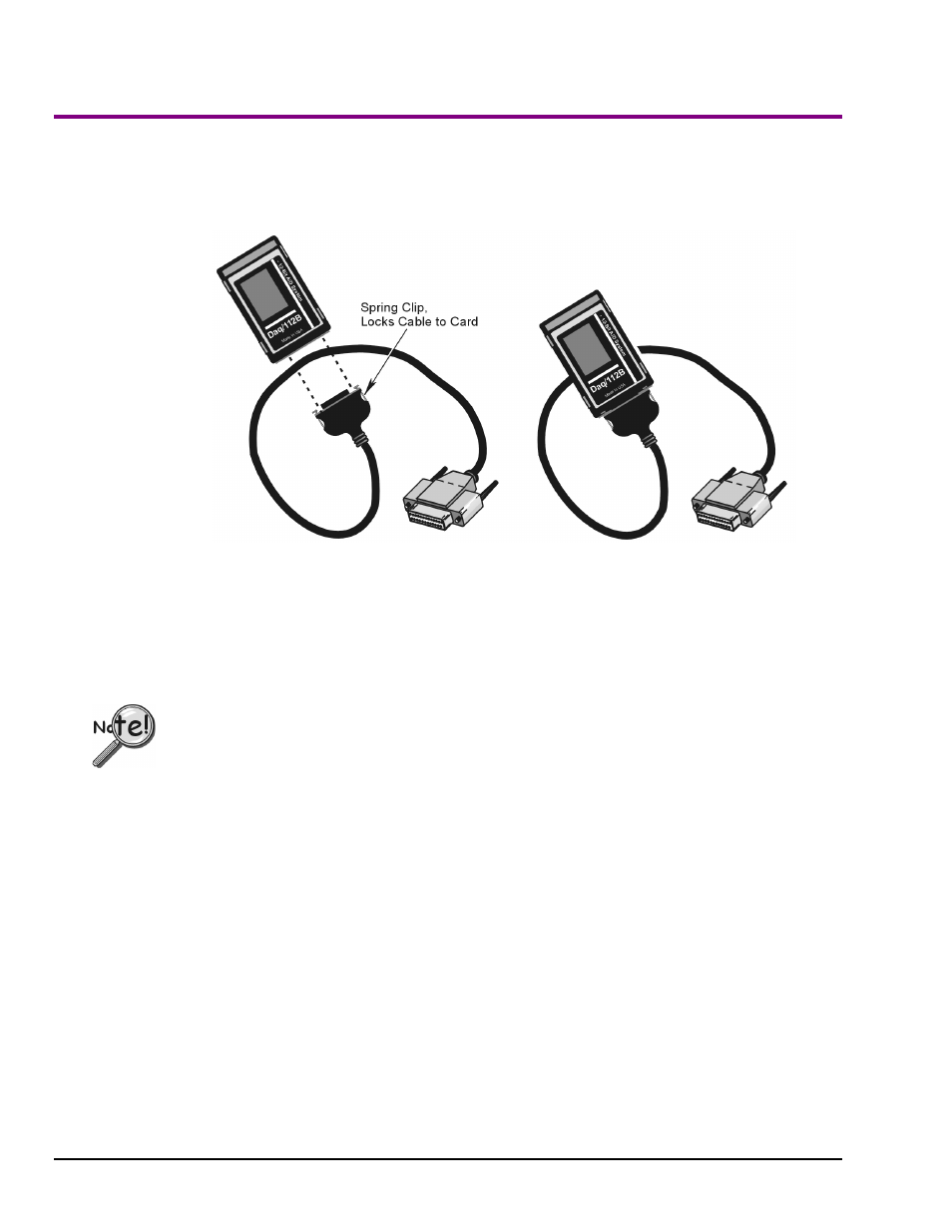
Daq/112B PC-Card, before and after attaching to a CA-134 Interface Cable
The CA-134 Interface Cable provides a female DB37 (P1) port for connecting a single passive DBK device
(such as DBK11 or DBK40) to the PC-Card. An included gender changer (CN-86, not shown) provides a
means of interfacing with a CA-37-x expansion cable. The CN-86 gender changer is also used when
connecting the PC-Card to a CDK10 module. Your user’s manual contains more detailed information,
including a pin-out of the DB37 (P1) interface.
Damage to the card or cable may result if not properly connected! Never force the connection. The
Daq PC-Card and cable are keyed, and should connect easily when properly oriented. Make sure the
connectors slide together at a level angle. Excessive or angular force can damage the connectors.
Follow these steps to connect the Daq PC-Card to the Interface Cable (CA-134).
1.
Hold the Daq PC-Card so that the label is face up and the bottom edge is facing you.
2.
Verify key alignment is correct for the card and the cable.
3.
Depress the cable’s spring-clips and connect the cable to the PC-Card.
4.
After connection is made, release the spring-clips.
Connecting to DBK Modules
Only DBK modules that support the DB37 (P1) connector can be used with Daq PC-Cards. If connecting
to a CA-37-x expansion cable, or to a CDK10 module, use the supplied gender changer (CN 86). Refer to
your user’s manual as needed.
1.
Plug the DB37 (P1) connector end of the Interface Cable into the compatible DBK module.
2.
Verify all connections before powering up the system.