Daqbook p2 pinout digital i/o – Measurement Computing Daq PC-Card User Manual
Page 39
Daq* Hardware
DaqBook/100, /112, /120, /200, /216
DaqBook/DaqBoard/Daq PC-Card User’s Manual
10-18-00
3-9
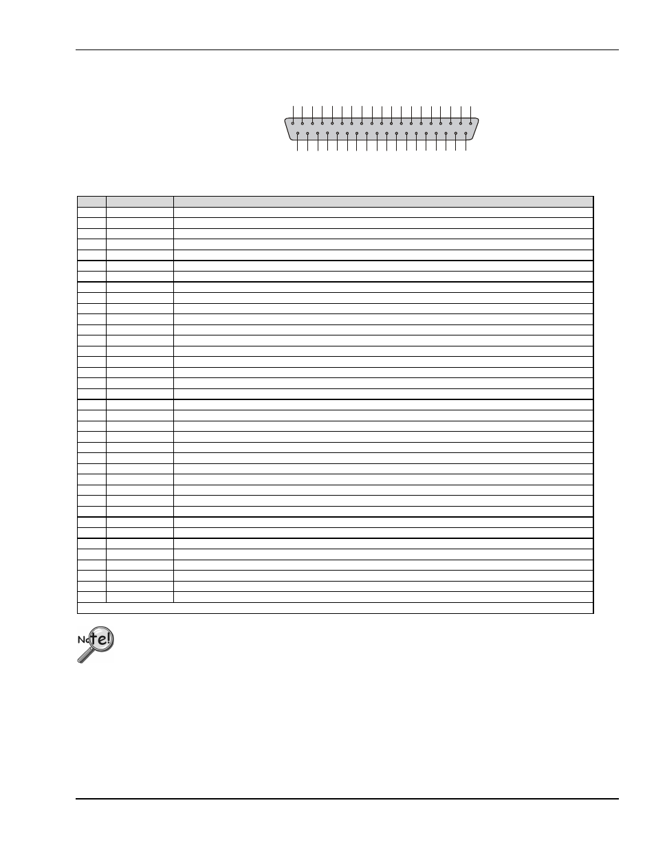
DaqBook
P2 Pinout
Digital I/O
This P2 interface is
available on the
DaqBook/100, /120,
/200, and /260.
1
9
G
N
D
P
O
R
T
A
0
3
7
P
O
R
T
A
1
3
6
P
O
R
T
A
2
3
5
P
O
R
T
A
3
3
4
P
O
R
T
A
4
3
3
P
O
R
T
A
5
3
2
P
O
R
T
A
6
3
1
P
O
R
T
A
7
3
0
P
O
R
T
C
0
2
9
P
O
R
T
C
1
2
8
P
O
R
T
C
2
2
7
P
O
R
T
C
3
2
6
P
O
R
T
C
4
2
5
P
O
R
T
C
5
2
4
P
O
R
T
C
6
2
3
P
O
R
T
C
7
2
2
G
N
D
2
1
+
5
V
2
0
8
P
O
R
T
B
2
7
P
O
R
T
B
3
6
P
O
R
T
B
4
5
P
O
R
T
B
5
4
P
O
R
T
B
6
3
P
O
R
T
B
7
2
I
R
E
N
A
B
L
E
1
IR
I
N
P
U
T
1
0
P
O
R
T
B
0
9
P
O
R
T
B
1
1
8
+
5
1
7
G
N
D
1
6
N
/C
1
5
G
N
D
1
4
N
/C
1
3
G
N
D
1
2
N
/C
11
G
N
D
Pin
Signal Name
Description for P2 Pin Use
1
IR INPUT
Interrupt line input (no functions to access this)
2
IR ENABLE
Interrupt line enable (no functions to access this)
3
PORT B 7
Digital input/output - port B bit 7
4
PORT B 6
Digital input/output - port B bit 6
5
PORT B 5
Digital input/output - port B bit 5
6
PORT B 4
Digital input/output - port B bit 4
7
PORT B 3
Digital input/output - port B bit 3
8
PORT B 2
Digital input/output - port B bit 2
9
PORT B 1
Digital input/output - port B bit 1
10
PORT B 0
Digital input/output - port B bit 0
11
GND
Digital ground
12
N/C
Pin not connected/not used
13
GND
Digital ground
14
N/C
Pin not connected/not used
15
GND
Digital ground
16
N/C
Pin not connected/not used
17
GND
Digital ground
18 +5 V +5 V supply (Refer to
Power Management
section in chapter 7)
19
GND
Digital ground
20 +5 V +5 V supply (Refer to
Power Management
section in chapter 7)
21
GND
Digital ground
22
PORT C 7
Digital input/output - port C bit 7
23
PORT C 6
Digital input/output - port C bit 6
24
PORT C 5
Digital input/output - port C bit 5
25
PORT C 4
Digital input/output - port C bit 4
26
PORT C 3
Digital input/output - port C bit 3
27
PORT C 2
Digital input/output - port C bit 2
28
PORT C 1
Digital input/output - port C bit 1
29
PORT C 0
Digital input/output - port C bit 0
30
PORT A 7
Digital input/output - port A bit 7
31
PORT A 6
Digital input/output - port A bit 6
32
PORT A 5
Digital input/output - port A bit 5
33
PORT A 4
Digital input/output - port A bit 4
34
PORT A 3
Digital input/output - port A bit 3
35
PORT A 2
Digital input/output - port A bit 2
36
PORT A 1
Digital input/output - port A bit 1
37
PORT A 0
Digital input/output - port A bit 0
Note: No local lines are available if digital expansion cards are in use.
P2 expansion cables must be kept short for proper operation. Do not exceed 14” per attached DBK card.